Sheldon said:I agree. Great discussion. Here's where I'm headed:
Couple of things.
The transformer ratios are backward. Should be 1:10 and 1:2. Also, if you're going to use the Sowter 1:10, with its low primary inductance, you're probably going to get some significant low frequency peaking using just 2.2uF coupling. Can't say much about the tube stage, but not sure a common-cathode circuit like that will be able to drive it.
Finally, instead of using a bias resistor on each of the JFET sources, use just one bias resistor at the center tap of the output (i.e. from center tap to ground). Having them on the sources needlessly increases the output impedance. On the center tap, the bias resistor is effectively out of the circuit under AC conditions.
se
Steve Eddy said:The transformer ratios are backward. Should be 1:10 and 1:2. Also, if you're going to use the Sowter 1:10, with its low primary inductance, you're probably going to get some significant low frequency peaking using just 2.2uF coupling. Can't say much about the tube stage, but not sure a common-cathode circuit like that will be able to drive it.
Maybe I just misunderstand the conventions. I have a swing of about 200 Volts at the plate of the 801. I want to reduce that to a swing of 20V to the FET's. Shouldn't that be a 10:1 step down ratio? The impedance of the output stage is about 4.5K at the primary. With a 10:1 stepdown (or however the proper notation), I should see a reflected impedance of 45 ohm, no?
On the output end of the follower, I would see a swing of a little less than 20V. If I step down 2:1 (1:2?), i'd get a swing of 10V. If I've calculated correctly (no certainty), that would give me about 6 watts, which is what I'm looking for. Right now I'm using a 37:1 (1:37?) transformer on the output, which gives me about 1/2 watt for my 100+ dB tweeter. I'll be using it from about 1kHz up.
Steve Eddy said:Finally, instead of using a bias resistor on each of the JFET sources, use just one bias resistor at the center tap of the output (i.e. from center tap to ground). Having them on the sources needlessly increases the output impedance. On the center tap, the bias resistor is effectively out of the circuit under AC conditions.
Yeah, I had considered that, but wasn't sure which way was best. I thought maybe individual resistors could force balance in the primary. I'd need something around 2-3ohms. But since I have matched FET's, maybe a common resistor is the call. I'll try with a common resistor first.
Thanks,
Sheldon
Choke loaded amp calcs
Hi Susan!
SE and choke loaded mosfet follower.
Yes, I know. What about, if I use Zobel in the X-over?
O.K. but the main question: am I right with the power calculation formulas of choke loaded amp???
for voltage limiting: (+U/1.414)2/Rload
for current limiting: Prms = Irms*Irms*R.
If it is so, than the 2 amps will let me swing to -16v into 8 ohms The supply rail will need to be +16v plus a couple of volts extra for the mosfet when swinging positive doesn't have to turn on too hard and going into it's nonlinear region.
Greets:
Tyimo
Hi Susan!
Is this SE or PP?
SE and choke loaded mosfet follower.
8 ohms is nominal, and most speakers will dip at some points a lot lower than this.
Yes, I know. What about, if I use Zobel in the X-over?
Also allow for the necessity to have some headroom (which varies with mosfet type) so you may want to allow for a couple of extra volts than the calc says.
O.K. but the main question: am I right with the power calculation formulas of choke loaded amp???
for voltage limiting: (+U/1.414)2/Rload
for current limiting: Prms = Irms*Irms*R.
If it is so, than the 2 amps will let me swing to -16v into 8 ohms The supply rail will need to be +16v plus a couple of volts extra for the mosfet when swinging positive doesn't have to turn on too hard and going into it's nonlinear region.
Greets:
Tyimo
Sheldon said:Maybe I just misunderstand the conventions.
No, I see now that you have it right. My mistake. Was just so used to seeing that input trannie for the output follower being a step-up in Susan's design I wasn't thinking you were actually intending it to be a step-down.
I've never been much of a fan of jacking up the gain in one place only to jack it back down someplace else so I'm always thinking in terms of either 1:1s or step-ups.
Yeah, I had considered that, but wasn't sure which way was best. I thought maybe individual resistors could force balance in the primary. I'd need something around 2-3ohms. But since I have matched FET's, maybe a common resistor is the call. I'll try with a common resistor first.
Yeah, if you could tweak the value of one or the other resistors you could ultimately null any offset. But if the FETs are already closely matched, there shouldn't be much off set to begin with.
se
Steve Eddy said:I've never been much of a fan of jacking up the gain in one place only to jack it back down someplace else so I'm always thinking in terms of either 1:1s or step-ups.
That's what we usually gotta do in the tube world, eh? But we don't jack down the power, only convert it from high voltage/low current, to the inverse.
Sheldon
nemestra said:An input transformer step up ratio of 2:1 would therefore suffice
...
Transformer impedance is proportional to the square of the turns ratio
As Steve has already gently pointed out this isn't the reason for the low input impedance in this case.
Pulled my copy of Handbook for Sound Engineers, 3rd. Ed, Glen Ballou and re-read chapter 11 - Audio Transformer Basics by Bill Whitlock of Jensen Transformers. The simple trade-off I suggested of voltage gain for input impedance is not so simple.
James
nemestra said:
As Steve has already gently pointed out this isn't the reason for the low input impedance in this case.
Pulled my copy of Handbook for Sound Engineers, 3rd. Ed, Glen Ballou and re-read chapter 11 - Audio Transformer Basics by Bill Whitlock of Jensen Transformers. The simple trade-off I suggested of voltage gain for input impedance is not so simple.
James
I think I get the general drift. Let's see if I'm even close.
I was thinking of using something like the Lundahl 1680 for a 9:1 step down. The primary is listed at 210H. If I read the tables correctly, that should give me a primary impedance of around 10K at 10Hz. If I use an termination resistor of around 1k, the input impedance would be 81k//10k, or around 9k at 10Hz. If I used a 100R termination resistor I'd have 9k//10k, or about 4.7k. I would think that would be ok for my purposes. Or am I way off here?
Sheldon
May I ask those in the US, where are you guys going to get the output transformers? Are you guys importing them from UK or finding an alternative local source?
nemestra said:Pulled my copy of Handbook for Sound Engineers, 3rd. Ed, Glen Ballou and re-read chapter 11 - Audio Transformer Basics by Bill Whitlock of Jensen Transformers. The simple trade-off I suggested of voltage gain for input impedance is not so simple.
Nope, it sure isn't.
And for those who don't have Ballou's book, Jensen finally has that chapter availabe on their website in pdf format.
Audio Transformers by Bill Whitlock
se
agent.5 said:May I ask those in the US, where are you guys going to get the output transformers? Are you guys importing them from UK or finding an alternative local source?
Susan posted the specs for the output transformer on her website. You might want to give the good folks at CineMag a call and see if they'd be willing to wind some and what they would charge for it.
se
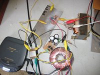
Apologies to Susan for asking a bunch of questions, then waiting so long to get to this. But, finally built the Mini Zeus with Lovaltech jFet's. Schematic follows, pic of breadboard on next post. It plays music, so time to put a case together and build the amp.
I wound the OPT's with 0.8mm wire (about 150 turns), trifilar, on EI112 cores with square bobbins. Gapped them with 0.075mm brass shim. The Fet's are soldered to a copper plate with low temperature solder, then bolted to the heat sink with mica insulators and thermal grease.
I have it biased at about 0.6A per device. One thing I didn't expect is that, under these conditions, the Fet gates draw about 0.5mA current. Don't guess that should be a problem though.
Sheldon
Attachments

Hey Sheldon,
I'm guilty as you except I haven't even got the fets soldered to copper bar yet - need to source low temp solder - where did you get it?
Also so many amps to build/tweak - SKA SS amp & Baby Huey Tube amp. Zeus would fit neatly in between these two, I think
Can't wait to hear your impressions of the sound
John
jkeny said:Hey Sheldon,
I'm guilty as you except I haven't even got the fets soldered to copper bar yet - need to source low temp solder - where did you get it?
Also so many amps to build/tweak - SKA SS amp & Baby Huey Tube amp. Zeus would fit neatly in between these two, I think
Can't wait to hear your impressions of the sound
John
Now that I have everything, I can play around. Even have a scope now, but have to pick up a signal generator and learn scope basics.
The solder is a brand called Tix Solder. Should be easy to find on the net. It's used by jewelry hobbiests.
Sheldon
Mini Zeus
Hi Sheldon,
I trust you (and everyone else) are keeping well.
Thank you for you post and project update, schematic and pictures.
Not a problem, I understand how long even "simple" projects can take.
I am currently building a new pair of Zeus 75 monoblocks with separate power supplies and I am still building the latter despite starting last November (2006). I have been fussing with the metalwork which always seems to take an inordinate amount of time despite having access to metalworking equipment.
On that note I did buy myself a Bosh GNA 2.0 sheet metal nibbler, which is worth looking at. It does have a mind of it's own, and really needs guides to constrain it when cutting. However it is still a vast improvement when cutting steel over a jig-saw which was really hard work for me.
http://www.axminster.co.uk/product.asp?src=07_wk21a&pricing=INC&pf_id=19838&
The amps are finished, except at some point will have to be disassembled to have their heatsinks anodised black.
My TX-102 preamp / line-driver was finished a month ago, and that one took me 14 months as I kept needing the TX-102s for bench testing.
Circuit as shown will need to be biased so always working in Class A (at 20 to 30 Hz). This is dependent on reflected load resistance, so match against the speaker's impedance curve which should be more lenient at the very low end than just a straight forward resistor.
If it hits Class B on a large swing the second FET will no longer balance the current flow and this will instead go through the common resistor to ground.
Can of course be "cured" with a large cap (e.g. 100,000 uF) which doesn't have to have a very high voltage rating (16 volts preferably just in case the cap is shown the power supply).
However the power supply inrush with be considerable, and some form of "soft start" would be needed to protect the FETs from over current. Perhaps a NTC anti-surge resistor in the supply?
The other way would be to use a standard mosfet between the reservoir cap and ground and turn it on with a R/C ramp so it went through a nice slow transition turn on. Add a reverse diode across the R to discharge the timing C quickly when power is removed to protect against fast cycling of the supply.
FET gate inputs should be (very) high impedance. Please excuse the question but you do have the zener diodes in the right way round? I know, but I have done this one myself so realize how easy it is to look at the part, check it out carefully, then fit them backwards!
In the past I have temporarily fitted a 1.0 ohm resistor between ground and the center tap of the input transformer secondary to measure current flow as mV whilst ensuring that the gates don't inadvertently get lifted.
---
Great stuff, hope all continues well.
Thanks.
Best wishes,
Susan.
Hi Sheldon,
I trust you (and everyone else) are keeping well.
Thank you for you post and project update, schematic and pictures.
Sheldon said:Apologies to Susan for asking a bunch of questions, then waiting so long to get to this. But, finally built the Mini Zeus with Lovaltech jFet's. Schematic follows, pic of breadboard on next post. It plays music, so time to put a case together and build the amp.
Not a problem, I understand how long even "simple" projects can take.
I am currently building a new pair of Zeus 75 monoblocks with separate power supplies and I am still building the latter despite starting last November (2006). I have been fussing with the metalwork which always seems to take an inordinate amount of time despite having access to metalworking equipment.
On that note I did buy myself a Bosh GNA 2.0 sheet metal nibbler, which is worth looking at. It does have a mind of it's own, and really needs guides to constrain it when cutting. However it is still a vast improvement when cutting steel over a jig-saw which was really hard work for me.
http://www.axminster.co.uk/product.asp?src=07_wk21a&pricing=INC&pf_id=19838&
The amps are finished, except at some point will have to be disassembled to have their heatsinks anodised black.
My TX-102 preamp / line-driver was finished a month ago, and that one took me 14 months as I kept needing the TX-102s for bench testing.
I wound the OPT's with 0.8mm wire (about 150 turns), trifilar, on EI112 cores with square bobbins. Gapped them with 0.075mm brass shim. The Fet's are soldered to a copper plate with low temperature solder, then bolted to the heat sink with mica insulators and thermal grease.
Circuit as shown will need to be biased so always working in Class A (at 20 to 30 Hz). This is dependent on reflected load resistance, so match against the speaker's impedance curve which should be more lenient at the very low end than just a straight forward resistor.
If it hits Class B on a large swing the second FET will no longer balance the current flow and this will instead go through the common resistor to ground.
Can of course be "cured" with a large cap (e.g. 100,000 uF) which doesn't have to have a very high voltage rating (16 volts preferably just in case the cap is shown the power supply).
However the power supply inrush with be considerable, and some form of "soft start" would be needed to protect the FETs from over current. Perhaps a NTC anti-surge resistor in the supply?
The other way would be to use a standard mosfet between the reservoir cap and ground and turn it on with a R/C ramp so it went through a nice slow transition turn on. Add a reverse diode across the R to discharge the timing C quickly when power is removed to protect against fast cycling of the supply.
I have it biased at about 0.6A per device. One thing I didn't expect is that, under these conditions, the Fet gates draw about 0.5mA current. Don't guess that should be a problem though.
FET gate inputs should be (very) high impedance. Please excuse the question but you do have the zener diodes in the right way round? I know, but I have done this one myself so realize how easy it is to look at the part, check it out carefully, then fit them backwards!
In the past I have temporarily fitted a 1.0 ohm resistor between ground and the center tap of the input transformer secondary to measure current flow as mV whilst ensuring that the gates don't inadvertently get lifted.
---
Great stuff, hope all continues well.
Thanks.
Best wishes,
Susan.
Lovoltech power JFET gate current
Hi Sheldon,
Hum, been looking through the Lovoltech datasheets...
... and find a graph titled "RDSON vs Gate Current" which clearly shows "significant" current being drawn.
http://www.qspeed.com/Products/JFET-Part-Listing.cfm
Given that this is described as a Power JFET it would seem then my understanding is skewed as I have always used JFETs for very high input impedance buffers etc. I am somewhat confused and guess I must be missing something.
http://en.wikipedia.org/wiki/JFET
Um...
... so basically these are not really depletion mode devices, there is something else going on as well?
Lovoltech, now Qspeed Semiconductor says in AN102:
"The gate junction of the power JFET is a p-n junction. When VGS (or VGD) is high enough to forward bias the gate p-n junction, a leakage current begins to flow through the gate."
http://www.qspeed.com/AppNotes/JFET/AN102-Understanding-Power-On-Resistance-Rdson.pdf
But for a Zeus one is working the other way round, but still there is some current flow. Minority current perhaps?
I have written to Qspeed to ask about this.
Someone more into the physics of these devices may be able to enlighten us on this effect (please)?
Best (confused) wishes,
Susan.
Hi Sheldon,
Hum, been looking through the Lovoltech datasheets...
I have it biased at about 0.6A per device. One thing I didn't expect is that, under these conditions, the Fet gates draw about 0.5mA current. Don't guess that should be a problem though.
... and find a graph titled "RDSON vs Gate Current" which clearly shows "significant" current being drawn.
http://www.qspeed.com/Products/JFET-Part-Listing.cfm
Given that this is described as a Power JFET it would seem then my understanding is skewed as I have always used JFETs for very high input impedance buffers etc. I am somewhat confused and guess I must be missing something.
http://en.wikipedia.org/wiki/JFET
Um...
... so basically these are not really depletion mode devices, there is something else going on as well?
Lovoltech, now Qspeed Semiconductor says in AN102:
"The gate junction of the power JFET is a p-n junction. When VGS (or VGD) is high enough to forward bias the gate p-n junction, a leakage current begins to flow through the gate."
http://www.qspeed.com/AppNotes/JFET/AN102-Understanding-Power-On-Resistance-Rdson.pdf
But for a Zeus one is working the other way round, but still there is some current flow. Minority current perhaps?
I have written to Qspeed to ask about this.
Someone more into the physics of these devices may be able to enlighten us on this effect (please)?
Best (confused) wishes,
Susan.
Re: Mini Zeus
Yes, very well. My pleasure to provide evidence of progress.
Yes, the casework is the most time consuming part. So far, I've built mine with non-ferrous metals and wood, so I can do most of my cutting with a table saw and a good blade. The nibbler is a good idea for more intricate work. I'll note that.
I'm not sure I understand the comments on the bias resistor. This amp doesn't really fit into the usual class A/B modes so neatly. I'll have to think some more. Until the light comes on, I assume you mean to bypass the bias resistor? Was wondering myself about the notion of a current source instead of the resistor? I have some IXYS parts I could use. BTW, I'm not concerned about the low end for this amp, as I have plenty of SS amps for that part of the signal, but would like to understand the principles.
I think these FET's can handle, short term, more current than my supply can deliver. I'll post the schematic.
I started with the Zeners the other way around, not recognizing that they would defeat the biasing - oops. So I removed them. After confirming that the circuit worked, I returned them in the direction shown. No difference to normal operation, but I wonder if I really need them.
I've been measuring current across the gate stoppers, and/or the input transformer secondaries, which are about 600Ohms. Wondering how necessary the gate stoppers are here, given the significant gate current.
Thanks so much,
Sheldon
Susan-Parker said:Hi Sheldon,
I trust you (and everyone else) are keeping well.
Thank you for you post and project update, schematic and pictures.
Yes, very well. My pleasure to provide evidence of progress.
Susan-Parker said:I am currently building a new pair of Zeus 75 monoblocks with separate power supplies and I am still building the latter despite starting last November (2006). I have been fussing with the metalwork which always seems to take an inordinate amount of time despite having access to metalworking equipment.
On that note I did buy myself a Bosh GNA 2.0 sheet metal nibbler, which is worth looking at. It does have a mind of it's own, and really needs guides to constrain it when cutting. However it is still a vast improvement when cutting steel over a jig-saw which was really hard work for me.
http://www.axminster.co.uk/product.asp?src=07_wk21a&pricing=INC&pf_id=19838&
Yes, the casework is the most time consuming part. So far, I've built mine with non-ferrous metals and wood, so I can do most of my cutting with a table saw and a good blade. The nibbler is a good idea for more intricate work. I'll note that.
Susan-Parker said:Circuit as shown will need to be biased so always working in Class A (at 20 to 30 Hz). This is dependent on reflected load resistance, so match against the speaker's impedance curve which should be more lenient at the very low end than just a straight forward resistor.
If it hits Class B on a large swing the second FET will no longer balance the current flow and this will instead go through the common resistor to ground.
Can of course be "cured" with a large cap (e.g. 100,000 uF) which doesn't have to have a very high voltage rating (16 volts preferably just in case the cap is shown the power supply).
However the power supply inrush with be considerable, and some form of "soft start" would be needed to protect the FETs from over current. Perhaps a NTC anti-surge resistor in the supply?
The other way would be to use a standard mosfet between the reservoir cap and ground and turn it on with a R/C ramp so it went through a nice slow transition turn on. Add a reverse diode across the R to discharge the timing C quickly when power is removed to protect against fast cycling of the supply.
I'm not sure I understand the comments on the bias resistor. This amp doesn't really fit into the usual class A/B modes so neatly. I'll have to think some more. Until the light comes on, I assume you mean to bypass the bias resistor? Was wondering myself about the notion of a current source instead of the resistor? I have some IXYS parts I could use. BTW, I'm not concerned about the low end for this amp, as I have plenty of SS amps for that part of the signal, but would like to understand the principles.
I think these FET's can handle, short term, more current than my supply can deliver. I'll post the schematic.
Susan-Parker said:
FET gate inputs should be (very) high impedance. Please excuse the question but you do have the zener diodes in the right way round? I know, but I have done this one myself so realize how easy it is to look at the part, check it out carefully, then fit them backwards!
In the past I have temporarily fitted a 1.0 ohm resistor between ground and the center tap of the input transformer secondary to measure current flow as mV whilst ensuring that the gates don't inadvertently get lifted.
I started with the Zeners the other way around, not recognizing that they would defeat the biasing - oops. So I removed them. After confirming that the circuit worked, I returned them in the direction shown. No difference to normal operation, but I wonder if I really need them.
I've been measuring current across the gate stoppers, and/or the input transformer secondaries, which are about 600Ohms. Wondering how necessary the gate stoppers are here, given the significant gate current.
Thanks so much,
Sheldon
Re: Lovoltech power JFET gate current
Yes, this confused me too, so I tried to do a bit of research. The gates are definitely negatively biased, so it's not forward gate current, as described in the data sheet graph. Though the gates are negative with respect to the source, they end up at a positive potential with respect to ground, so I'm thinking it must be what is described as reverse leakage current. I'm assuming (hoping), that it doesn't affect the input impedance of the device.
That said, I haven't absolutely confirmed that I didn't harm these two devices somehow, and I will check that. But their static measurements are the same as all the samples I have (pin to pin resistance, polarities, etc.).
Sheldon
edit: here's the power supply
Susan-Parker said:Hi Sheldon,
Hum, been looking through the Lovoltech datasheets...
... and find a graph titled "RDSON vs Gate Current" which clearly shows "significant" current being drawn.
http://www.qspeed.com/Products/JFET-Part-Listing.cfm
Given that this is described as a Power JFET it would seem then my understanding is skewed as I have always used JFETs for very high input impedance buffers etc. I am somewhat confused and guess I must be missing something.
http://en.wikipedia.org/wiki/JFET
Um...
... so basically these are not really depletion mode devices, there is something else going on as well?
Lovoltech, now Qspeed Semiconductor says in AN102:
"The gate junction of the power JFET is a p-n junction. When VGS (or VGD) is high enough to forward bias the gate p-n junction, a leakage current begins to flow through the gate."
http://www.qspeed.com/AppNotes/JFET/AN102-Understanding-Power-On-Resistance-Rdson.pdf
But for a Zeus one is working the other way round, but still there is some current flow. Minority current perhaps?
I have written to Qspeed to ask about this.
Someone more into the physics of these devices may be able to enlighten us on this effect (please)?
Best (confused) wishes,
Susan.
Yes, this confused me too, so I tried to do a bit of research. The gates are definitely negatively biased, so it's not forward gate current, as described in the data sheet graph. Though the gates are negative with respect to the source, they end up at a positive potential with respect to ground, so I'm thinking it must be what is described as reverse leakage current. I'm assuming (hoping), that it doesn't affect the input impedance of the device.
That said, I haven't absolutely confirmed that I didn't harm these two devices somehow, and I will check that. But their static measurements are the same as all the samples I have (pin to pin resistance, polarities, etc.).
Sheldon
edit: here's the power supply
Attachments
Re: Re: Lovoltech power JFET gate current
Ah, I didn't quite catch all of this before my previous reply. The inrush issue would result from the use of the large bypass cap. Will keep that in mind.
Sheldon
Susan-Parker said:Circuit as shown will need to be biased so always working in Class A (at 20 to 30 Hz). This is dependent on reflected load resistance, so match against the speaker's impedance curve which should be more lenient at the very low end than just a straight forward resistor.
If it hits Class B on a large swing the second FET will no longer balance the current flow and this will instead go through the common resistor to ground.
Can of course be "cured" with a large cap (e.g. 100,000 uF) which doesn't have to have a very high voltage rating (16 volts preferably just in case the cap is shown the power supply).
However the power supply inrush with be considerable, and some form of "soft start" would be needed to protect the FETs from over current. Perhaps a NTC anti-surge resistor in the supply?
The other way would be to use a standard mosfet between the reservoir cap and ground and turn it on with a R/C ramp so it went through a nice slow transition turn on. Add a reverse diode across the R to discharge the timing C quickly when power is removed to protect against fast cycling of the supply.
Ah, I didn't quite catch all of this before my previous reply. The inrush issue would result from the use of the large bypass cap. Will keep that in mind.
Sheldon
- Home
- Amplifiers
- Solid State
- Zero Feedback Impedance Amplifiers