Hi Susan!
Thanks for the answer!
Basicaly there are 2 different amp versions with I would like to try the output transformer:
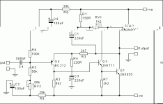
-JLH69 with dual supply(+/-22V) and no output cap. (the attached schem.) In there I could use toroid transformer.
-a mosfet follower amp (now with CCS: Bias 2A 30Vdc) There I need to use EI gapped transformer.
I think the first one has no problem and in the second one I would redesign the amp without CCS like in yours. Maybe it would be something like a choke loaded follower?
Please help me to learn how to design and calculate the output transormer for both (and different kind) amp!
Ca. 15W on 8 ohm
Greets:
Tyimo
Thanks for the answer!
Basicaly there are 2 different amp versions with I would like to try the output transformer:
-JLH69 with dual supply(+/-22V) and no output cap. (the attached schem.) In there I could use toroid transformer.
-a mosfet follower amp (now with CCS: Bias 2A 30Vdc) There I need to use EI gapped transformer.
I think the first one has no problem and in the second one I would redesign the amp without CCS like in yours. Maybe it would be something like a choke loaded follower?
Please help me to learn how to design and calculate the output transormer for both (and different kind) amp!
What power are you looking for and what sort of load (4ohms, 8ohm, ...)?
Ca. 15W on 8 ohm
Greets:
Tyimo
Attachments
Tyimo said:
Basicaly there are 2 different amp versions with I would like to try the output transformer:
-JLH69 with dual supply(+/-22V) and no output cap. (the attached schem.) In there I could use toroid transformer.
-a mosfet follower amp (now with CCS: Bias 2A 30Vdc) There I need to use EI gapped transformer.
I think the first one has no problem and in the second one I would redesign the amp without CCS like in yours. Maybe it would be something like a choke loaded follower?
Tyimo
Hi Tyimo!
Transformer load instead CCS load in source follower can
probably improve the sound, but why you need transformer for JLH?
This is direct coupled topology amplifier.
there was another thread on this subject....... he just wants to find out how it sounds.......
I guess a two way filter on the output has advantages - no ultra sonic garbage in or out.
sounds like a good idea to me
I wonder why I did try it yet ...
sounds like a good idea to me
I wonder why I did try it yet ...
he just wants to find out how it sounds.......
Thanks unclejed613! Thats it.🙂
Greets:
Tyimo
Hi Tyimo,
Power of 15W on 8 ohm is nice and sensible!
For the first version where you just want to experiment with transformer coupling with a 1:1 ratio you can use the secondary pair of a mains toroid transformer.
Would recommend something of 200VA or bigger, the main thing is getting enough turns so you really want one with an output of 55 + 55 Vac (or thereabouts, but not lower than 45 Vac). Higher is okay as long as the windings are bifilar wound otherwise you won't get the coupling.
For the second version you need a gapped core. This is most easily done with EI laminations but I have seen gapped toroid cores although not in standard pre wound mains transformers.
If you were very adventurous you could get a toroid core and slit it to make a gap (being careful that all the bits don't go "sprung") but I suspect this is being a bit over the top.
For SE version tri-filar wind three wires about 150 turns and then put two in series for the primary and the third is the secondary.
For small powers the EI120 size core should be fine, however you will be limited on current for biasing to get the number of turns for the wire diameter.
N.B. the given current rating for wire is normally given in free air and one has to derate by at least 60% for winding on a EI core (after Partridge article in Wireless World 1938 Dec 15th p529-530) and for larger transformers by 75%.
18 AWG (1.00 mm) is 2.36 A in air.
14 AWG (1.60 mm) is 6.0 A in air.
12 AWG (2.00 mm) is 9.4 A in air.
I run my EI120 transformers with 1.00 mm wire at 0.75 A per winding. With 12 AWG wire a max of c. 2.8 A per winding is indicated.
Remember that the SE transformer stores the energey required to go in the opposite sense to the supply rail in it's inductance so these higher biases are not fancy but necessity.
For a toroid with its large surface area to winding section the derating is much lower and with mains transformers the (max) current is normally specified for the windings.
In theory the larger the core cross section and the greater the gap that one uses (which needs more winding turns to maintain inductance) the lower the iron distortion will be. However other factors come into play so optimizing one factor does not necessarily give benefit to all others.
Best wishes,
Susan.
Tyimo said:Basicaly there are 2 different amp versions with I would like to try the output transformer:
-JLH69 with dual supply(+/-22V) and no output cap. (the attached schem.) In there I could use toroid transformer.
-a mosfet follower amp (now with CCS: Bias 2A 30Vdc) There I need to use EI gapped transformer.
I think the first one has no problem and in the second one I would redesign the amp without CCS like in yours. Maybe it would be something like a choke loaded follower?
Please help me to learn how to design and calculate the output transformer for both (and different kind) amp!
Power of 15W on 8 ohm is nice and sensible!
For the first version where you just want to experiment with transformer coupling with a 1:1 ratio you can use the secondary pair of a mains toroid transformer.
Would recommend something of 200VA or bigger, the main thing is getting enough turns so you really want one with an output of 55 + 55 Vac (or thereabouts, but not lower than 45 Vac). Higher is okay as long as the windings are bifilar wound otherwise you won't get the coupling.
For the second version you need a gapped core. This is most easily done with EI laminations but I have seen gapped toroid cores although not in standard pre wound mains transformers.
If you were very adventurous you could get a toroid core and slit it to make a gap (being careful that all the bits don't go "sprung") but I suspect this is being a bit over the top.
For SE version tri-filar wind three wires about 150 turns and then put two in series for the primary and the third is the secondary.
For small powers the EI120 size core should be fine, however you will be limited on current for biasing to get the number of turns for the wire diameter.
N.B. the given current rating for wire is normally given in free air and one has to derate by at least 60% for winding on a EI core (after Partridge article in Wireless World 1938 Dec 15th p529-530) and for larger transformers by 75%.
18 AWG (1.00 mm) is 2.36 A in air.
14 AWG (1.60 mm) is 6.0 A in air.
12 AWG (2.00 mm) is 9.4 A in air.
I run my EI120 transformers with 1.00 mm wire at 0.75 A per winding. With 12 AWG wire a max of c. 2.8 A per winding is indicated.
Remember that the SE transformer stores the energey required to go in the opposite sense to the supply rail in it's inductance so these higher biases are not fancy but necessity.
For a toroid with its large surface area to winding section the derating is much lower and with mains transformers the (max) current is normally specified for the windings.
In theory the larger the core cross section and the greater the gap that one uses (which needs more winding turns to maintain inductance) the lower the iron distortion will be. However other factors come into play so optimizing one factor does not necessarily give benefit to all others.
Best wishes,
Susan.
Hi Susan!
Thank you very much in deed for your kind help!
If I understand correct for the first 1:1 transformer variation: I have to make on a ca. 300VA toroid core 55+55 Vac bifilar windings. O.K. It is not a problem!
For the second version /Mosfet follower/: EI120 transformers with airgap, tri-filar wind three 1.35mm wires about 150 turns,etc.
O.K. It is also not a problem! What gap size do you sugest me? 0.25-0.30mm??
I like this idea very much, because I know a man, who has a little toroid maker workshop and I think He could help me to create such a gaped toroid.....🙂
One more question. The follower amp with OTP would act like like a choke loaded follower? I mean the bias and power efficiency.
uuhh, one more question!😀
Could you give me the theory and the math for these calculations you did? I would like to understand and learn it.
Greets:
Tyimo
Thank you very much in deed for your kind help!
If I understand correct for the first 1:1 transformer variation: I have to make on a ca. 300VA toroid core 55+55 Vac bifilar windings. O.K. It is not a problem!
For the second version /Mosfet follower/: EI120 transformers with airgap, tri-filar wind three 1.35mm wires about 150 turns,etc.
O.K. It is also not a problem! What gap size do you sugest me? 0.25-0.30mm??
If you were very adventurous you could get a toroid core and slit it to make a gap (being careful that all the bits don't go "sprung") but I suspect this is being a bit over the top.
I like this idea very much, because I know a man, who has a little toroid maker workshop and I think He could help me to create such a gaped toroid.....🙂
One more question. The follower amp with OTP would act like like a choke loaded follower? I mean the bias and power efficiency.
uuhh, one more question!😀
Could you give me the theory and the math for these calculations you did? I would like to understand and learn it.
Greets:
Tyimo
Hi Tyimo,
Yes, you can just use a standard mains toroid, and ignore the mains primary winding.
Yes. Use copper foil or paper. I use copper.
Nice, please let me know how you get on if you try this.
Yes, except one has to factor in the turns ratio for the load.
Math?
The transformer derating information is from a published article by Partridge as per previous post. Basically he did a series of tests and measured heat rise in various transformer cores relative to current and wire gauge.
So a wire that has a certain capacity stretched out in free air can't be treated the same as many windings in a small cubic space as in a transformer bobbin.
The rest has been mostly trial and error (lots of the latter) and these figures are the "rule of thumb" that works for me.
Best wishes,
Susan.
Tyimo said:If I understand correct for the first 1:1 transformer variation: I have to make on a ca. 300VA toroid core 55+55 Vac bifilar windings. O.K. It is not a problem!
Yes, you can just use a standard mains toroid, and ignore the mains primary winding.
For the second version /Mosfet follower/: EI120 transformers with airgap, tri-filar wind three 1.35mm wires about 150 turns,etc.
O.K. It is also not a problem! What gap size do you sugest me? 0.25-0.30mm??
Yes. Use copper foil or paper. I use copper.
I like this idea very much, because I know a man, who has a little toroid maker workshop and I think He could help me to create such a gaped toroid.....🙂
Nice, please let me know how you get on if you try this.
One more question. The follower amp with OTP would act like like a choke loaded follower? I mean the bias and power efficiency.
Yes, except one has to factor in the turns ratio for the load.
uuhh, one more question!😀
Could you give me the theory and the math for these calculations you did? I would like to understand and learn it.
Math?
The transformer derating information is from a published article by Partridge as per previous post. Basically he did a series of tests and measured heat rise in various transformer cores relative to current and wire gauge.
So a wire that has a certain capacity stretched out in free air can't be treated the same as many windings in a small cubic space as in a transformer bobbin.
The rest has been mostly trial and error (lots of the latter) and these figures are the "rule of thumb" that works for me.
Best wishes,
Susan.
i use a lot of bifilar (and trifilsr as well) windings, both for audio, and ham radio applications. i have a technique for creating nice looking wire for this. use two different colors of wire (so the winding is easy to identify). calculate how long a wire you need for the winding (add about 10% for the bifilar process i use, plus "winding slop"). measure your wires, and clamp the ends of them side by side in a vise about 1/2" apart. stretch them out across the room, and clamp the other ends in the chuck of a variable speed drill. SLOWLY use the drill to twist the wires evenly until you have the desired twist pitch (usually i use about a 1/4" pitch for #24 wire, a 3/8" pitch for #18, a 1/2"pitch for #16). use the twisted wire to wind your toroid. bifilar usually twists pretty evenly, trifilar requires a bit of extra care to keep the twists even and in sequence (one wire, if it is even slightly longer than the other two, has a tendency to "jump" it's sequence, which really doesn't affect performance, but looks lousy). be aware that there is a lot more capacitive cross-coupling with bifilar windings than there is with stacked windings and opposed windings (one winding on one side of the toroid, the other winding on the opposite side). it's not as much a consideration at audio frequencies as it is at RF, but it's there. once you get your transformer wound, you can measure the inter-winding capacitance directly.
Hi unclejed613
Thanks for your post.
This technique is great for keeping the multi-filar windings together but one needs to watch out (particularly if one is making bobbins for an EI transformer) as the twisting will decrease the number of turns one can get in a given space.
For hand winding a toroid this is a good way of keeping the wires together and one doesn't need that many twists to keep everything together. Be careful of pressure points where the wires cross over each other on a corner.
Interwinding capacitance will be in the nF range, however with the small number of turns, the low driving impedance, and the fact that all windings are seeing the same voltage swing this isn't a problem as the output bandwidth is still a couple of MHz (with my EI120 transformer).
Looking at the transformer spec page (3/4ths way down)...
http://www.audiophonics.com/audiophonics-zeus-out-tx-75w.html
... you will see that in 2:1 mode there is about 10nF between primary and secondary.
Many thanks.
Best wishes,
Susan.
[M1009 + RT-524 + R-442 + PRC-77]
Thanks for your post.
unclejed613 said:... SLOWLY use the drill to twist the wires evenly until you have the desired twist pitch...
This technique is great for keeping the multi-filar windings together but one needs to watch out (particularly if one is making bobbins for an EI transformer) as the twisting will decrease the number of turns one can get in a given space.
For hand winding a toroid this is a good way of keeping the wires together and one doesn't need that many twists to keep everything together. Be careful of pressure points where the wires cross over each other on a corner.
Interwinding capacitance will be in the nF range, however with the small number of turns, the low driving impedance, and the fact that all windings are seeing the same voltage swing this isn't a problem as the output bandwidth is still a couple of MHz (with my EI120 transformer).
Looking at the transformer spec page (3/4ths way down)...
http://www.audiophonics.com/audiophonics-zeus-out-tx-75w.html
... you will see that in 2:1 mode there is about 10nF between primary and secondary.
Many thanks.
Best wishes,
Susan.
[M1009 + RT-524 + R-442 + PRC-77]
Hi Susan!
I would like to ask something about choke loaded amps power calculations, maybe you can help me!
I know, if I ignore stuff like saturation voltage and losses in the choke, just divide the rail voltage by 1,414, square the result and divide by the load impedance.
(+U/1.414)2/Rload
But, what about the current??? How will I know that my amp is voltage limited or current limited into any given load?????
I need to know this, because I would like to bias the amp for the correct level.
I know this formula for current limit calculation:
Prms = Irms*Irms*R.
Irms = 0,707*Ipeak
Ipeak is my bias current.
for example with 2A bias:
Irms=2*0,707=1,414Arms
Prms(I)=1,414*1,414*8=16Wrms
What would be the correct supply voltage with 2A bias and 8 ohm load? ca.16V??
Greets:
Tyimo
Hi Susan, and everyone else!
I'm only on page 90 yet, but thought I'd chime in and say that this thread was extremely interesting, and I will be looking to try to implement Susan's design as soon as I can. Time to start looking for old transformers that can be used for experimentation, I suppose!
Regards
I'm only on page 90 yet, but thought I'd chime in and say that this thread was extremely interesting, and I will be looking to try to implement Susan's design as soon as I can. Time to start looking for old transformers that can be used for experimentation, I suppose!
Regards
Patrik Floding said:I'm only on page 90 yet...
Only on page 90!?!?

You need to go to the user cp and set your options for 50 posts per page. Then you'll only have 23 pages to read. 😀
se
Hi Tyimo,
Is this SE or PP?
8 ohms is nominal, and most speakers will dip at some points a lot lower than this.
For SE inductance determines the LF response as well as the current one is using for the bias.
For PP the current sets the transition point for Class A to AB.
Also allow for the necessity to have some headroom (which varies with mosfet type) so you may want to allow for a couple of extra volts than the calc says.
Best wishes,
Susan.
Tyimo said:...
What would be the correct supply voltage with 2A bias and 8 ohm load? ca.16V??
Is this SE or PP?
8 ohms is nominal, and most speakers will dip at some points a lot lower than this.
For SE inductance determines the LF response as well as the current one is using for the bias.
For PP the current sets the transition point for Class A to AB.
Also allow for the necessity to have some headroom (which varies with mosfet type) so you may want to allow for a couple of extra volts than the calc says.
Best wishes,
Susan.
Hi,
I've been following this thread since its inception and have been (slowly) constructing a pair of Zeus 75s. These have strictly followed Susan's circuit and use all her recommended parts.
Configuration
Input transformer: Sowter 8160 with 50% mumetal laminations in 5:1 configuration (primaries in series)
Output transformer: Sowter 9840 in 4:1 configuration
Mosfets: STW34NB20s Vgs matched to < 1mV at 500mA in test jig
Bias: 750mA per Mosfet supplied by L200 tracking current source
Heatsink: 0.2/W SK158 300x200x80 from Dau
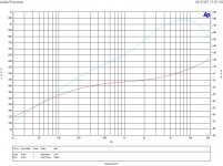
I've encountered the difficulties mentioned frequently by Susan in driving this power amplifier. A variety of DACs and preamps objected to its the low input impedance (stated to be 600 ohm). I'm currently constructing some line drivers, AD845+THAT1646 and AD8610+THAT1646 based. The THAT chip, a recently introduced line driver, has an output impedance of around 60 ohms maximum. Before finishing these off I decided to run an Audio Precision across the design to determine if this line driver would function well.
In the attached graph the cyan curve shows the input impedance. The input signal level was 500 mV. At high frequencies ~8kHz the input impedance is approximately 900 ohms - low but can be driven by a source with a low output impedance. By 600Hz it has fallen to 600 ohms - a standard reference value. As the frequency decreases to 20Hz the Zeus75 input impedance drops to 120 ohms. This is a very difficult load for most preamps and perhaps explains Susan's like of 'chunky' preamps 🙂
James
I've been following this thread since its inception and have been (slowly) constructing a pair of Zeus 75s. These have strictly followed Susan's circuit and use all her recommended parts.
Configuration
Input transformer: Sowter 8160 with 50% mumetal laminations in 5:1 configuration (primaries in series)
Output transformer: Sowter 9840 in 4:1 configuration
Mosfets: STW34NB20s Vgs matched to < 1mV at 500mA in test jig
Bias: 750mA per Mosfet supplied by L200 tracking current source
Heatsink: 0.2/W SK158 300x200x80 from Dau
I've encountered the difficulties mentioned frequently by Susan in driving this power amplifier. A variety of DACs and preamps objected to its the low input impedance (stated to be 600 ohm). I'm currently constructing some line drivers, AD845+THAT1646 and AD8610+THAT1646 based. The THAT chip, a recently introduced line driver, has an output impedance of around 60 ohms maximum. Before finishing these off I decided to run an Audio Precision across the design to determine if this line driver would function well.
In the attached graph the cyan curve shows the input impedance. The input signal level was 500 mV. At high frequencies ~8kHz the input impedance is approximately 900 ohms - low but can be driven by a source with a low output impedance. By 600Hz it has fallen to 600 ohms - a standard reference value. As the frequency decreases to 20Hz the Zeus75 input impedance drops to 120 ohms. This is a very difficult load for most preamps and perhaps explains Susan's like of 'chunky' preamps 🙂
James
Attachments
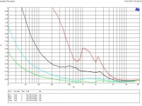
In view of this difficult load I decided to investigate the THD+N characteristics. The input signal level was 500 mV and the measurement bandwidth was 22Hz to >500kHz. The curves in order:
red - source output impedance = 600 ohms
black - source output impedance = 150 ohms
cyan - source output impedance = 50ohms
green - source output impedance = 25 ohms
I was tempted to drag in a conventional power amplifier to provide a <0.1 ohm source impedance but the trend is already clear. As can be seen, not unexpectedly, the distortion decreases as the source impedance is reduced. I can now see that my line driver with its 40-60 ohm output impedance will not be a good match for this.
James
Attachments
There are five solutions that I see:
(1) Take the low impedance preamp route that Susan has pursued with transformer, headphone and AD815 designs.
(2) Modify the Zeus 75 to have a higher input impedance. I see several ways of doing this. In the Zeus designs voltage gain is provided by input transformer. Running of 34V rails the output Mosfets will run out of steam about a volt below this (being conservative, allowing for loading). Most line drivers running off +/18V can be persuaded to supply 16V peaks.
An input transformer step up ratio of 2:1 would therefore suffice. This necessarily locks the Zeus to sources which can supply higher outputs than normal. This is fine as the Zeus is such a unique design that being coupled to a specific (or small range) of preamps is unavoidable.
Transformer impedance is proportional to the square of the turns ratio. Thus the impedance reflected from the secondary input is divided by 25 with the current 1:5 step up transformer. With the substitution of a 1:2 step-up the impedance reflection is 4:1 which should increase the input impedance across the audio bandwidth signficantly and make the Zeus considerably easier to drive.
The next three ideas are based around creating a two stage design.
(3) Change the Zeus75 to have two stages, input/interstage and interstage/output. In a sense this is what Susan's transformer based preamp and the current Zeus75 already are. The two box solution requires four transformers. In effect the preamp output transformer and the power amp input transformer are merged into an interstage tranformer, saving costs.
This question has already been asked back in post #1076
http://www.diyaudio.com/forums/showthread.php?postid=1043464#post1043464
Susan's comments re. bandwidth are relevant and yet to be tackled.
(4) Change the Zeus75 to have two stages but allow (non transformer) voltage amplification in the first stage. This is what
Rozak has done in his design where the cascoded BF245C provides some voltage gain.
http://www.diyaudio.com/forums/showthread.php?postid=636682#post636682
However, philosophically this is difficult as it breaks Susan's idea of using wire based amplification only.
(5) Use a combination of ideas from (2) and (3). Again use a source which can provide a higher than normal swing. The problem of the b/w of the interstage transformer can be solved by making it a 1:1 ratio or 1:2 step-up. The voltage follower on the input can use lower power and lower capacitance FETs and thus the input impedance should be higher since the reflected Xc^2 will be much lower for FETs with Crss of a few pF.
None of the above should be viewed as critism of the existing design - Susan has produced and supported one of the more unusual and interesting designs seen here. I've had a lot of fun building them. With a sunk cost of 500 UKP in transformers and 200 UKP in heatsinks in addition to batches of MOSFETs I'm not about to let this one go. I'm simply offering some ideas on how the main quirk of the Zeus75 - the low input impedance could be tamed. I'm still as enthusiastic about this design as when I first saw it...
James
nemestra said:Transformer impedance is proportional to the square of the turns ratio. Thus the impedance reflected from the secondary input is divided by 25 with the current 1:5 step up transformer. With the substitution of a 1:2 step-up the impedance reflection is 4:1 which should increase the input impedance across the audio bandwidth signficantly and make the Zeus considerably easier to drive.
I think the input impedance issue with the current transformer isn't so much the turns ratio as it is the relatively miniscule primary inductance. Keep in mind that the primary inductance is in parallel with the reflected impedance and constitutes the limiting factor at low frequencies.
Anyway, I think the best approach would be moving the bulk of the voltage gain upstream using some good quality micrphone input trannies.
se
nemestra said:[B Susan has produced and supported one of the more unusual and interesting designs seen here. I'm still as enthusiastic about this design as when I first saw it...
[/B]
I agree. Great discussion. Here's where I'm headed:
Sheldon
Attachments

- Home
- Amplifiers
- Solid State
- Zero Feedback Impedance Amplifiers