Hi Sheldon,
Yes, this is preferable.
Generating the minus bias volts...
In theory it could be simply with a battery, but as previously discussed these seems to be some significant gate current drain so it wouldn't be practical for operation (although fine for short term testing).
You can wind a few turns of insulated enameled wire (I assume you have a bit left over from winding the output transformers) evenly spaced on the power supply toroid transformer to get an extra secondary for the bias supply. Then all you need is a bridge rectifier and cap. As you are winding the turns yourself you can increase/decrease the number of turns to get the exact bias voltage you want.
You also get a higher output voltage swing as you no longer lose the voltage across the bias resistor, which for a 12 volt supply system probably equates to several Watts.
Best wishes,
Susan.
Sheldon said:As an alternative to the large cap, what are the relative merits of fixed bias, such as this? With an adjustable bias supply, it wouldn't be any simpler than the original Zeus, but pretty easy to do.
Yes, this is preferable.
Generating the minus bias volts...
In theory it could be simply with a battery, but as previously discussed these seems to be some significant gate current drain so it wouldn't be practical for operation (although fine for short term testing).
You can wind a few turns of insulated enameled wire (I assume you have a bit left over from winding the output transformers) evenly spaced on the power supply toroid transformer to get an extra secondary for the bias supply. Then all you need is a bridge rectifier and cap. As you are winding the turns yourself you can increase/decrease the number of turns to get the exact bias voltage you want.
You also get a higher output voltage swing as you no longer lose the voltage across the bias resistor, which for a 12 volt supply system probably equates to several Watts.
Best wishes,
Susan.
Susan-Parker said:[BYes, this is preferable.
Generating the minus bias volts...
In theory it could be simply with a battery, but as previously discussed these seems to be some significant gate current drain so it wouldn't be practical for operation (although fine for short term testing).
You can wind a few turns of insulated enameled wire (I assume you have a bit left over from winding the output transformers) evenly spaced on the power supply toroid transformer to get an extra secondary for the bias supply. Then all you need is a bridge rectifier and cap. As you are winding the turns yourself you can increase/decrease the number of turns to get the exact bias voltage you want.
You also get a higher output voltage swing as you no longer lose the voltage across the bias resistor, which for a 12 volt supply system probably equates to several Watts.
[/B]
Thanks Susan,
Yes, picking up a couple extra volts of output swing for free is worthwhile. The simple design is appealing from an asthetic point of view, but simplicity just for simplicity's sake can be taken too far.
The extra winding is a nice idea, but I may want to regulate. My concern is that the idle current could get too high if the line voltage dropped, as the curve of ID vs. VGS is quite steep. The resistance on the OPT primary is only about 0.6R or so and would not provide much degeneration, so a modest change in line voltage could result in a pretty significant change in bias current. Yea/nay?
Sheldon
Hi Sheldon,
My pleasure.
Agreed.
Supply voltage will also drop, and here what one is more interested is in watts dissipation since the parts are rated at 50 amps.
I am not sure how linear the ratio will be, but I would have thought over normal expected supply variation it should be okay.
And the odd brownout will be a transitory voltage fluctuation I assume? Here in the UK we have quite good supply maintenance although our normalized 230 Vac where I am is running at 245 Vac!
Using a higher voltage and a regulator will of course give better stability and reduce the ripple pickup (although it is push-pull, still some does get into the output as the mosfets are never perfectly matched).
The last time I added secondaries to a mains toroid I needed between 3 and 4 turns per volt.
Best wishes,
Susan.
Sheldon said:Thanks Susan,
My pleasure.
Yes, picking up a couple extra volts of output swing for free is worthwhile. The simple design is appealing from an asthetic point of view, but simplicity just for simplicity's sake can be taken too far.
Agreed.
The extra winding is a nice idea, but I may want to regulate. My concern is that the idle current could get too high if the line voltage dropped, as the curve of ID vs. VGS is quite steep. The resistance on the OPT primary is only about 0.6R or so and would not provide much degeneration, so a modest change in line voltage could result in a pretty significant change in bias current. Yea/nay?
Supply voltage will also drop, and here what one is more interested is in watts dissipation since the parts are rated at 50 amps.
I am not sure how linear the ratio will be, but I would have thought over normal expected supply variation it should be okay.
And the odd brownout will be a transitory voltage fluctuation I assume? Here in the UK we have quite good supply maintenance although our normalized 230 Vac where I am is running at 245 Vac!
Using a higher voltage and a regulator will of course give better stability and reduce the ripple pickup (although it is push-pull, still some does get into the output as the mosfets are never perfectly matched).
The last time I added secondaries to a mains toroid I needed between 3 and 4 turns per volt.
Best wishes,
Susan.
Thanks Again,
You are right, the voltage doesn't fluctuate that much, or for that long, so probably nothing to worry about. I'll play around and see how it goes.
BTW, with the low melting temperature solder, I can actually make a free heat fuse. The solder that I used to bond the fet to the copper plate, melts at about 145 degrees C. The B+ is connected to the copper plate. So if I have a little tension on the other leads to the fet, and the temperature rises about 145, then the fet will release from the plate and disconnect from the power supply.
Sheldon
Hi Sheldon,
Could you say a little more about this low temp solder?
Do you have any idea where I could pick up a real small
quanity of it say a 1/10 of an oz or so.
Could you say a little more about this low temp solder?
Do you have any idea where I could pick up a real small
quanity of it say a 1/10 of an oz or so.
Testing I did. Did about 15 turns on the ps toroid, into a bridge and a couple of RC sections (25R,470u, then 75R 450uF). Added a 560R bleeder resistor, and I get about -2.4V. I calculated that I need a bias voltage between gate and source of about 1.7V. So far, so good.
BUT, when I hook this up through the transformer, the Fet's conduct like crazy and the power supply voltage drops almost in half. If I hook up the bias supply direct to the gates, no conduction (expected, as bias should be about -1.7 and the bias supply is -2.4). If I substitute resistors of about the same DC resistance of the transformer, no conduction. So, the transformer must be causing oscillation. I tried gate stoppers up to about 700R to no effect. So I'm kinda at a dead end here. It may be back to self bias, because of the oscillation.
But, there is another reason too, and it has to do with the high level of reverse gate leakage. If there is no resistance in the gate to ground, or gate to bias supply, no problem. But, if there is resistance in the path, the voltage at the gate goes up as significant current flows from drain to source. If there is enough negative bias to control the gate under operating conditions, the bias will be too high before current begins to flow. So, the system has to be jump started by briefly disconnecting the bias supply. Goofy, eh?
Maybe time to look at some smaller convential Mosfets. I guess I could use a small fet source follower to drive the gates, but that's getting away from the wonderful simplicity of the design.
Sheldon
woody said:Hi Sheldon,
Could you say a little more about this low temp solder?
Do you have any idea where I could pick up a real small
quanity of it say a 1/10 of an oz or so.
Quite a few sources on the net. It's not expensive.
Sheldon
Hi Sheldon,
I just ordered some from here: http://www.ares-server.com/Ares/Ares.asp?MerchantID=RET01229&Action=Catalog&Type=Product&ID=17110
I ordered the Tix soldering flux and anti flux as well - just in case I might be repairing clocks or jewellery in the future. Inexpensive at $32 including postage to Ireland.
Now need to source copper bar to solder onto and I'm in business.
Any advice at this stage Sheldon? I guess I should use the flux and do what you did - heat copper bar with blow torch until solder melts then apply Fet to solder with pressure - did you use some tool for this?
Thanks & keep up the good work
John
jkeny said:Hi Sheldon,
I just ordered some from here: http://www.ares-server.com/Ares/Ares.asp?MerchantID=RET01229&Action=Catalog&Type=Product&ID=17110
I ordered the Tix soldering flux and anti flux as well - just in case I might be repairing clocks or jewellery in the future. Inexpensive at $32 including postage to Ireland.
Now need to source copper bar to solder onto and I'm in business.
Any advice at this stage Sheldon? I guess I should use the flux and do what you did - heat copper bar with blow torch until solder melts then apply Fet to solder with pressure - did you use some tool for this?
Thanks & keep up the good work
John
I clamped the cleaned copper bar in a vise and applied a small amount of flux. Then I cut a section of solder about 1cm long and bent it in a V shape. Place the V on the bar and then center the FET on the V. Gently heat the bar, until the solder melts, then push the FET down firmly against the bar (I used the eraser end of a pencil) and hold it for 10-20 seconds until the solder hardens. Done.
If you need to reposition it, no problem, just reheat gently to remelt the solder. The melting temperature of the solder is below the allowed operating temperature of the FET.
Sheldon
Thanks Sheldon,
What size copper bar do you use?
You've got both Fets on the one copper bar so both drains are electrically connected together & to B+ (11V). This is insulated from heatsink proper I believe.
Trafos - you didn't try the toroid route first but went straight to Lundahl & winding your own - how difiicult was winding your own?
What are you planning to drive the amp with?
Sorry for all the Q's but I consider myself still an apprentice.
John
jkeny said:Thanks Sheldon,
What size copper bar do you use?
You've got both Fets on the one copper bar so both drains are electrically connected together & to B+ (11V). This is insulated from heatsink proper I believe.
Trafos - you didn't try the toroid route first but went straight to Lundahl & winding your own - how difiicult was winding your own?
What are you planning to drive the amp with?
Sorry for all the Q's but I consider myself still an apprentice.
John
The bar is essentially twice the size of a TO-247 package, about 3mm thick. I used two mica insulators of that size to insulate it from the heatsink. Of course, you could use a single copper piece half that size for each transistor.
Winding was not too difficult. The hard part was getting the bits to do it. Since I wanted 2:1, i just wound three wires at the same time and used two for the center tapped primary and the third for the secondary. Of course, an off the shelf toroid would be even easier. But I wanted to try winding a trafo anyway.
I'm going to drive it with a DEQX. This device has an output impedance of 75 Ohms and the output full scale has five possible settings, from 1Vrms to 4.4Vrms. A setting of 2V rms should give me a swing of about =/- 11V (2*1.4*4) at the fet gates. The 1.5V setting would give me a swing of 8V, which will be near the maximum, if I use the self biasing approach.
I also plan to try it by reversing the input transformer to give 4:1 and then drive it from the plate of a tube amp. The amp is resistively loaded, with a parafeed style cap to the OPT. In this case, I would bypass the OPT and connect the high voltage feed to the input transformer of the mini zeus. The termination resistor would be about 625 ohms to give me a reflected impedance to the tube of about 10K. The tube amp/zeus combo would give me a full scale input sensitivity of about 1Vrms.
Sheldon
I've mulled this one over in my limited understanding of electronic design and have come to the following conclusions (take with a large grain of salt):
It's possible to use the Lovoltech devices, but the maximun power supply voltage should be 12V (absolute max. of 13V). At 12V a swing of about +- 10V can be achieved at the primary, as around 2V is required to bias the FETs'.
I think, because of the strange reverse current on the gates, they don't like any inductance on the gate. Means they can't be biased through the transformer, as Susan's design is. Further, I don't see any simple way to cap couple the input transformer to the gates and used a fixed bias on the gates. That would require a relative high impedance bias source, but the reverse current at the gate fights against it and, since it increases somewhat with increased current in the FET, it would create a positive feedback and cause the FET to go wide open.
So, we're stuck with a resistor (and big cap, as Susan pointed out, if we don't want full class A bias current). For about 1Amp total bias current, it seems to require about 1.7V across the bias resistor, so an alternative to the resistor and cap is about 70 cheap LED's wired in parallel, with the color chosen to suit the desired bias current (could have fun with that one).
Or, maybe go back to Susan's design, but for a mini version use something like an STP16NF06L, a TO220 mosfet, which looks like a scaled down version of the STW34NB 20. I'm going to get a batch of those to try (they are inexpensive).
I've had some very interesting PM correspondance with a DIY member regarding possible alternative drive schemes for the mosfet, which I'd like to compare at some point. But they need testing first.
Sheldon
Sheldon,
I am sure you have read the Zen Version 9 thread at the Pass forum. Why not cascode the LU1014s to get best linearity (if that was your motivation in using them in the first place). They are two possible ways, one like Nelson Pass does at about 1.3A bias, one like what I do (see the MOSFET headamp thread of Grey Rollins) at 0.3A bias.
http://www.diyaudio.com/forums/showthread.php?postid=1130939#post1130939
With my very limited experience with the LU1014s, I would suspect that your JFETs are possibly damaged. Anything other than a few uA on the gate is suspect at least. They are FETs, not bipolars !!!
Best regards,
Patrick
You may be right Patrick, cause your circuit or the Pass circuit couldn't work with the current I see back through the gate. My unloaded supply has an output voltage of about 13.5V. The maximum Vgs is -12V. That's the only maximum I could have exceeded. The only thing I can think of is if I had the gate disconnected with the source open, then the potential from gate to source, when the gate was connected could have exceeded -12V. Been working more with tubes and sometimes forget that these little sand things are intolerant of mistakes, even for an instant.
I'll have to try some new ones.
Sheldon
I'll have to try some new ones.
Sheldon
Is this right configuration for the output transformer?
I have read through this thread and trying to understand the build-up configuration of the output transformer. Is the attached picture correctly interprets the information in this thread?
I have read through this thread and trying to understand the build-up configuration of the output transformer. Is the attached picture correctly interprets the information in this thread?
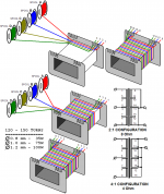
I assume that the two bobbins shown represent two halfs of a split bobbin. As I intrepret your figure, you have all the primaries on one side, and the secondaries on the other side. I think the intent is to have the primaries and secondaries wound together. So, for instance, the windings from one bobbin should be in series with the windings from the second bobbin, with the taps taken at the junction between the bobbin halves. In principle it's the same as winding on a single bobbin but looping out for a center tap, at the halfway count.
Sheldon
Sheldon
Re: Zeus output quad-fillar transformer configuration
Hi,
Nice picture, I appreciate the time and effort to make this.
For the three wire diameters one would also use three different sizes of bobbins which roughly ratio to give similar(ish) number of turns.
0.8 mm = EI 1-1/4" (EI-125)
1.0 mm = EI 1-1/2" (EI-150)
1.2 mm = EI 2" (EI-200) or EI 2-1/8" (EI-212)
If one only wants to operate in 2:1 then one can wind a single section bobbin (which will look much like the illustration). This is simple and can be done by hand (or on a simple rig with a large hand drill held in a bench vice).
A dual section bobbin needs a bit more sophistication as it is desirable to match both sides to be the same number of turns. Given the nature of transformers and the winding interleaving a small mismatch of one or two turns will work acceptably.
My original Zeus 35 prototype transformers were wound on a single chamber bobbin in two layer sections and they are unlikely to be perfectly matched for turns and the outer section will have a higher DC resistance anyway.
The nature of the interleaving is as Sheldon describes (thanks for that).
The idea is to use one winding from each side for the two primaries, and the corresponding sections or all in parallel for the secondaries. This ensures maximum coupling between the two mosfets and should compensate for any small mismatches between the two sections. The all paralleled secondaries can likewise be a little mismatched between pairs as this should even out in operation.
Looking at my web page:
http://www.audiophonics.com/audiophonics-zeus-out-tx-75w.html
I see that it could use a wiring diagram as well, which I will add.
The reason I use quad filar windings and two secondaries in 2:1 or four secondaries in 4:1 is to do with copper cross section area and balancing current flow. I also want a nice low DC resistance to act as a brake for the speaker driver's linear (one hopes) motor.
Whilst that is how I have the habit of doing things, I am sure that Tri-filar winding is fine particularly for 2:1 and lower wattages.
And it is worth hand winding one's own transformers if one can, the savings can be significant.
Thanks for the continued interest in this thread.
Best wishes,
Susan.
Hi,
bokakob said:Oops - did not realise that after "preview" I had to re-attach the file.
Nice picture, I appreciate the time and effort to make this.
For the three wire diameters one would also use three different sizes of bobbins which roughly ratio to give similar(ish) number of turns.
0.8 mm = EI 1-1/4" (EI-125)
1.0 mm = EI 1-1/2" (EI-150)
1.2 mm = EI 2" (EI-200) or EI 2-1/8" (EI-212)
Sheldon said:I assume that the two bobbins shown represent two halfs of a split bobbin. As I intrepret your figure, you have all the primaries on one side, and the secondaries on the other side. I think the intent is to have the primaries and secondaries wound together. So, for instance, the windings from one bobbin should be in series with the windings from the second bobbin, with the taps taken at the junction between the bobbin halves. In principle it's the same as winding on a single bobbin but looping out for a center tap, at the halfway count.
If one only wants to operate in 2:1 then one can wind a single section bobbin (which will look much like the illustration). This is simple and can be done by hand (or on a simple rig with a large hand drill held in a bench vice).
A dual section bobbin needs a bit more sophistication as it is desirable to match both sides to be the same number of turns. Given the nature of transformers and the winding interleaving a small mismatch of one or two turns will work acceptably.
My original Zeus 35 prototype transformers were wound on a single chamber bobbin in two layer sections and they are unlikely to be perfectly matched for turns and the outer section will have a higher DC resistance anyway.
The nature of the interleaving is as Sheldon describes (thanks for that).
The idea is to use one winding from each side for the two primaries, and the corresponding sections or all in parallel for the secondaries. This ensures maximum coupling between the two mosfets and should compensate for any small mismatches between the two sections. The all paralleled secondaries can likewise be a little mismatched between pairs as this should even out in operation.
Looking at my web page:
http://www.audiophonics.com/audiophonics-zeus-out-tx-75w.html
I see that it could use a wiring diagram as well, which I will add.
The reason I use quad filar windings and two secondaries in 2:1 or four secondaries in 4:1 is to do with copper cross section area and balancing current flow. I also want a nice low DC resistance to act as a brake for the speaker driver's linear (one hopes) motor.
Whilst that is how I have the habit of doing things, I am sure that Tri-filar winding is fine particularly for 2:1 and lower wattages.
And it is worth hand winding one's own transformers if one can, the savings can be significant.
Thanks for the continued interest in this thread.
Best wishes,
Susan.
Lovoltech devices
Hi Sheldon,
Thank you for your update.
I remain puzzled by the Lovoltech device's behavior.
I also haven't had any reply from my email asking for clarification (will let you know if I hear anything).
I would go with Patrick's possibility of gate damage, but the normal use turn on current is something that to me seems to indicate that there may be something else going on.
And Mr Nelson Pass's Zen 8 & 9 variation circuits use the LU1014D as a gain stage, so the operation is different to here.
Hum...
... still puzzled.
Best wishes,
Susan.
Hi Sheldon,
Thank you for your update.
Sheldon said:I've mulled this one over in my limited understanding of electronic design and have come to the following conclusions...
I remain puzzled by the Lovoltech device's behavior.
I also haven't had any reply from my email asking for clarification (will let you know if I hear anything).
I would go with Patrick's possibility of gate damage, but the normal use turn on current is something that to me seems to indicate that there may be something else going on.
And Mr Nelson Pass's Zen 8 & 9 variation circuits use the LU1014D as a gain stage, so the operation is different to here.
Hum...
... still puzzled.
Best wishes,
Susan.
- Home
- Amplifiers
- Solid State
- Zero Feedback Impedance Amplifiers