
Another reason: It is not as graphically interesting.....

Do you listen with your eyes?
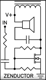
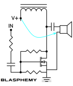
Umm, way out of my depth here, but the Schade resistor would no longer be taking feedback from the speaker, just the choke?Job interview question for people applying to be a designer at Pass Labs: Discuss a few reasons why the blasphemous variation below, is less desirable than the Zenductor original.
Well ok, since we're talking about this circuit, I have a question about the resistor divider network.
In the DC domain, it's a voltage divider that sets the gate bias. Simple enough, and that's how I selected the resistance values I used, to target an approximate gate bias. In the AC domain, since this is a common source topology, the signal on the drain pin is amplified and inverted relative to the gate, thus sampling some amount of that signal back to the gate provides feedback (or, throwing Schade, haha). The amount of feedback presumably is in proportion to the ratio of the two resistance values, as the second resistor references to ground.
I'm not knowledgeable enough to know how to solve for both AC and DC characteristics simultaneously. Assuming one has to do this serially, which does one favor when selecting values, a given operating point or a given amount of feedback?
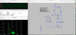
No, that’s wrong. Think again.I don't think the ACA feedback loop has any significant effect on the high pass frequency of the RC fliter . It is mainly determined by the speaker impedance in conjunction with the capacitor.
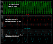
a quick-and-dirty "what if" in the circuit simulator appears to suggest otherwise; the blasphemy version appears to put less power supply noise across the speaker, not more.One possible reason, I think - power supply noise is cancelled.
Have some fun with it yourself; make some assumptions, slap together a "spice deck" {boy am I old} , and horse around. See what there is to be seen.
_
Attachments
I think that the modified version will be better, as the current draw from the power supply will be allmost constant, because the load is in parallel with the mosfet not the choke. That will more or less take the power supply out of the curcuit.Job interview question for people applying to be a designer at Pass Labs: Discuss a few reasons why the blasphemous variation below, is less desirable than the Zenductor original.
😉 Thorsten
I would give the answer by @thorstenlarsen a score of +2 if I were on the interview committee. Congratulations and well done!
Then I would ask a followup question. To quote the Monte Python film Time Bandits: Nelson and Mike are "Not Entirely Dim." There must be some other way of looking at the circuit ... some other evaluation criterion ... by which the original surpasses the blasphemous? Or are you saying that blasphemous is universally better and also that you are smarter than Nelson Pass and Mike Rothacher put together?"
Then I would ask a followup question. To quote the Monte Python film Time Bandits: Nelson and Mike are "Not Entirely Dim." There must be some other way of looking at the circuit ... some other evaluation criterion ... by which the original surpasses the blasphemous? Or are you saying that blasphemous is universally better and also that you are smarter than Nelson Pass and Mike Rothacher put together?"
The combined bias/feedback network bothers me a bit, as a good portion of the input signal seems to be shunted to ground by the resistor between gate and ground. Perhaps DC bias and AC feedback can be separated, as per the lower LazyCad schematic?
Attachments
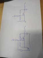
"Perhaps DC bias and AC feedback can be separated, as per the lower LazyCad schematic?"
I don't think there's enough time to get this change onto the B.A.F.2023 PCBs and to purchase the new parts, in time for the Build Camp just one month from now (??)
You would have to (a) obtain approval from the BAF committee for the change; (b) lay out a new PCB with the changes; (c) get the PCB fabricated with expedited shipping; (d) order all new components and have them shipped to the right people, well in advance of BAF; (e) create new schematic and parts list and build guide
while time is short.
Oh, I'm just thinking loud here. B.A.F. is half a world away from where I live. I'm 100% sure the circuit designed for the B.A.F. event works just fine, I just had this idea that it might be a bit wasteful to have a voltage divider at the input when there's only a single transistor there to provide all the gain.
And I don't claim to have invented anything, I believe the ZV2 differs from ZV1 in the exact same manner as I have drawn here.
And I don't claim to have invented anything, I believe the ZV2 differs from ZV1 in the exact same manner as I have drawn here.
True. BTW, my drawing with AC coupled feedback wouldn't work if the speaker is connected between + and output.
I don' think this project is interview puzzle material or some special exercise in engineering optimization. It's a fun, beginner-friendly, iron-fortified, great-sounding return to my flea-watt salad days of dog-eared AA and Sound Practices issues, the smell of solder smoke, and Zen - the little amp that shifted a few paradigms, broke a few rules, and introduced a new generation to our hobby. That was the point of this one. Come up with (quickly) something super simple and fun that can be assembled in a camp setting in a few hours and immediately enjoyed. You may blame me for anything you deem to be dumb, but the proof of the pudding is in the eating. And, being smarter than me wouldn't really be an especially resume-worthy achievement. 🙂
- Home
- Amplifiers
- Pass Labs
- Zenductor