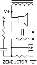

Finally, if my eyes and brain are not deceiving me, a new power transconductance/current source (obvious, it is a Zen, no? Choke loaded and no CCS. Pa if so as usual delivers on his promises, in this case a few years back in either the F2 or Alpair 12P thread.
MZM: I did order this from OPLDF!
Tony: If my lousy interpretation is correct, interaction with the load is a minimal issue with a current source. Plus I gather phase will be inverted too so inverse connecting the speaker wires is advise, if at all relevant for your concern.
Wonder if there are some tickets left for BAF, may join on video 🙂
All wrong? Perhaps, I think not, but I don’t really care: exciting news anyways!
Choke also takes care of DC so no output cap needed
Cap in series with speaker.
Seen, edited the post but you beat me to it (shoulda just written eddited to correct). With inversed output that makes sense, and in any case - DC residual or not - it would take care of thumps.
Added: Also, it doesn’t look is deprived of Iq as suggested. The L and two resistors (possible resistor networks G-Vpos/L and G-Vneg will take care of that, I would imagine. Not quite like on the F2, but perhaps in principle yes.
Added: Also, it doesn’t look is deprived of Iq as suggested. The L and two resistors (possible resistor networks G-Vpos/L and G-Vneg will take care of that, I would imagine. Not quite like on the F2, but perhaps in principle yes.
Last edited:
I'll add this because Nelson's too modest. They sound fantastic! And I had a LOT of well-regarded SE triode (and otherwise) amps on hand for comparison. 🙂
Yes, unless you can put up with the .8V DC offset across the speaker.Cap in series with speaker.
I refer you to my BAF comments and measurements about putting some DC bias through speakers.....

Modesty my *ss, this was your idea, and you will get your share of the blame.I'll add this because Nelson's too modest. They sound fantastic! And I had a LOT of well-regarded SE triode (and otherwise) amps on hand for comparison. 🙂

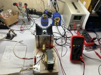
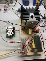
Well that was a fun afternoon! And yes, it plays music but I don't want to comment too much, it's only an IRFP240 😉
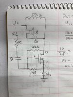
Edit: okay wait, if you're going to try this yourself, the upper cap needs to be in the milifarads, not 5uF. Hyooge difference.
Edit: okay wait, if you're going to try this yourself, the upper cap needs to be in the milifarads, not 5uF. Hyooge difference.
Attachments

Last edited:

So. By way of beating the drum, here's my Zenductor graphic.
yeah, as I said - Very Bad Papa

I was sleepy, so couldn't find it pronto, but it did remind me of ........ when double No is still No
I am Spartacus 🙂Modesty my *ss, this was your idea, and you will get your share of the blame.
Really cool!!!Well that was a fun afternoon! And yes, it plays music but I don't want to comment too much, it's only an IRFP240 😉
Edit: okay wait, if you're going to try this yourself, the upper cap needs to be in the milifarads, not 5uF. Hyooge difference.
I don't think the ACA feedback loop has any significant effect on the high pass frequency of the RC fliter . It is mainly determined by the speaker impedance in conjunction with the capacitor.
I had trouble sleeping last night thinking about that resonant circuit. It seems like it can be modeled as an RLC where the R is the frequency-dependent impedance of the speaker. So if one has a speaker with a free-air resonance at 75Hz of ~100 ohms, does that mean that the LC should or should not be tuned to that same resonant frequency? In the case of a 50mH choke, 90uF would resonate at 75Hz. Would that destroy the speaker? It seems like it would have the exact opposite effect of a shunt resistor, as is sometimes done to reduce the resonance peak.
- Home
- Amplifiers
- Pass Labs
- Zenductor