I always preffer voltage multipliers as they have lower ripple with multiplying factor and also offer a degree of protection in case of short circuit, but for a tube preamp that protection is kinda useless...
I've been using current-fed push-pull DC-DC converters powered by a switching wall wart to run my VT preamp and headphone amp projects. I even have a moderate-sized SE amp using 6L6GC and 6AH6 powered by a medium-sixed DC-DC running from a switching 24V/5A adapter. The DC to DC circuits are all unregulated, and rely on the line/load regulation of the switching adapter that precedes them.
I do the same but 12V/50A ATX and I've used it to power a KT88 PP stereo amp.
I wouldn't even mind designing an SMPS for a tube amp that made 12V from the line for heaters and the DC was boosted from 12V but all on one board 🙂
I wouldn't even mind designing an SMPS for a tube amp that made 12V from the line for heaters and the DC was boosted from 12V but all on one board 🙂
These days I favor a DC-DC approach for supplying power to a vacuum tube application, keeping the nasty AC interface in a box that already has the appropriate safety certifications . I would never market a straight AC to DC design due to concerns with safety and liability. The Chinese do it all the time, but that doesn't mean I have to....
Last edited:

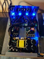
What’s “the silencer” pointing at? That is by far the largest fan I have ever seen.Medium to high power: https://www.aliexpress.com/item/1005003336586371.html
low power: https://www.aliexpress.com/item/1005001756069951.html
Good for VU meters or nixies: https://www.aliexpress.com/item/33040159635.html
Here's the PSU for my preamp 🙂 The picture is before it was completely wired.
View attachment 1072956
Well, yes, HVDC does kill people who don't watch where their fingers are poking, but there is a lot of due diligence that has to be performed to release an AC-DC power supply, including EMI compliance, safety compliance, line surge withstand, ESD resistance, etc. I doubt that most of the suppliers from over there have done due diligence. I would rather run a DC-DC off an SMPS from a major supplier that has the applicable safety ratings. There is too much that can go wrong otherwise.
Your right, never trust the specs. Just make your own experience by try it out. And share it on diyaudio.
Seconded,These days I favor a DC-DC approach for supplying power to a vacuum tube application, keeping the nasty AC interface in a box that already has the appropriate safety certifications . I would never market a straight AC to DC design due to concerns with safety and liability. The Chinese do it all the time, but that doesn't mean I have to....
There is a Polish supplier that makes 12VDC to 450V 100mA flyback cores. The downside of this approach is higher primary currents, and EMI.
https://www.tme.eu/nl/details/ti-ef25-1068/pcb-transformatoren/feryster/
I made a 12V=>450V board some time back.
Attachments

It's just a standard/fancy PC power supply.What’s “the silencer” pointing at? That is by far the largest fan I have ever seen.
https://www.pcpowerandcooling.com/product/mkiii-500w/
Thanks PRR, I didn’t realise it was a supply. It seems to look much flatter in the photos.
I’m trying to cool some power resistors at the moment (load box) and looking around for options.
I’m trying to cool some power resistors at the moment (load box) and looking around for options.
This is the general form of the DC-DC converter I've been using to power various vacuum tube projects. I have various boards including the outputs necessary. For example, for a headphone amp project, the board will be a small one, with only the HV output, set for +150V, with the filaments of the project running from the switching adapter used to to power the project in question.. The higher power converter I'm using to power my 6L6GC/6AH6 single-ended amp uses the filament output at 12V and the HV output, set to 400 VDC, with a larger transformer to handle the power in question.
The DC-DC runs near 100% duty cycle, with a small amount of drive overlap programmed in so that the current-fed push-pull works properly. The regulation comes from the regulated SMPS used to drive the converter - this works well in practice, and the regulation is superior to that obtained from a conventional 60Hz transformer-based design.
The DC-DC runs near 100% duty cycle, with a small amount of drive overlap programmed in so that the current-fed push-pull works properly. The regulation comes from the regulated SMPS used to drive the converter - this works well in practice, and the regulation is superior to that obtained from a conventional 60Hz transformer-based design.
Attachments

T1 is unregulated...and its output depends entirely on the load. a resonant converter takes 2...4 trz , a coil and a capacitor plus same T1 and it's output is a sinus while having similarly regulated output only by the load.Your noise depends on the 12v source noise...
It's not a resonant converter at all, it's a current-fed push-pull The design is unregulated. It gets its regulation from the switching adapter that feeds it.I wind my own transformers. I've been designing switching power supplies of various sorts for over 40 years.
Well it's not, anyway, and I would never consider a resonant converter for a DC-DC application - the circulating currents would be pretty high.
I am going to use a back to back transformer from 12v smps should yield 150 to 200v regulated for 60w tube amp. 2nd transformer from PC power supply.
Using a transformer from a PC power supply in a DC-DC application might be problematic, It would depend on the topology of the donor power supply. If the donor supply uses a 1/2 bridge topoolgy, you might be OK, as there would probably be a center-tapped winding for the 12V output. If the donor supply uses a 2-transistor forward topology, there will be a single winding for the 12V output, probably stacked on top of the 5v output. This would be much harder to use as you envision.
Last edited:
- Home
- Amplifiers
- Power Supplies
- Who can/will help me with highvoltage SMPS design for tube preamp