Mr. Worf, raise shields...
Man, it blows my mind that everyone seems to have their "own way" of wiring a project like this. Out of any of the fundamentals that I am trying to learn, grounding seems to bring out the most conflicting views in forums.
I don't understand what a shield does. Consider the chassis... It is apparently good to house your PCB's in a metal enclosure. I'm guessing this helps to protect it from RF noise and a little bit of EM fields? I sure wouldn't think that attaching the metal frame to the circuit's ground would make it less noisey but in my experience it does. It lowers noise by about 10dB (depending on the project). Why is this?
The RCA cable uses it's ground for shielding. XLR's do not attach the ground to shield. Why? If the shield and the ground of an XLR eventually make contact in the Pre, why not just use the ground as a shield instead?
I have read things so far that discuss different parts of a circuit as being "upstream" and describing a river that flows from low current into higher currents. For example this picture that I grabbed from one of Zero D's posts illustrates this by moving the signal star away from the power star:
In anyone's experience, has following this practice lowered noise?
Thanks again, for all of the responses everyone, big thumbs up!
Attachments

Last edited:
I have, ... many times.You should explain you reasoning - it's the only way we can get a discussion and learn that way.
After that it's becomes a case of those that want to believe in good wiring practice and those that blindly "star ground" without thinking about the routes that the currents are forced to follow by tortuous wiring errors.
Start with Henry Otts information...
http://www.hottconsultants.com/pdf_files/aes-2007.pdf
Henry Ott, excellent info on grounding....
home page
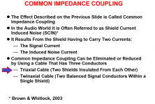
Bill Whitlock
JENSEN TRANSFORMERS, INC. - APPLICATION PAPERS AND SCHEMATICS
http://www.hottconsultants.com/pdf_files/aes-2007.pdf
Henry Ott, excellent info on grounding....
home page
Bill Whitlock
JENSEN TRANSFORMERS, INC. - APPLICATION PAPERS AND SCHEMATICS
Shredhead, if you design/build the system for best audio and noise abilities, then place it in a box, not relying on the ability of a piece of sheet metal to fix or cause any noise problems.
This seems like another design error. The XLR to Pre consists of one ground/shield (pin 1) and two signal wires. the pre should have balanced inputs without the signal wires directly connecting to ground.The RCA cable uses it's ground for shielding. XLR's do not attach the ground to shield. Why? If the shield and the ground of an XLR eventually make contact in the Pre, why not just use the ground as a shield instead?
Henry Ott, excellent info on grounding....
home page
Bill Whitlock
JENSEN TRANSFORMERS, INC. - APPLICATION PAPERS AND SCHEMATICS
I have read these and rane's interconnect guide and it seems to focus on connecting pieces of equipment together. Do you know of any in depth explanations of the best way to wire a preamp's internals (especially grounding method) for lowest noise?
Shredhead, if you design/build the system for best audio and noise abilities, then place it in a box, not relying on the ability of a piece of sheet metal to fix or cause any noise problems.
-My question is what is the explanation for attaching the ground to the box lowering noise? Isn't that a good thing that it does?
This seems like another design error. The XLR to Pre consists of one ground/shield (pin 1) and two signal wires.
I was referring to the arrow in this picture because that style of cable has been mentioned in this thread.
Attachments
Last edited:
I have read these and rane's interconnect guide and it seems to focus on connecting pieces of equipment together. Do you know of any in depth explanations of the best way to wire a preamp's internals (especially grounding method) for lowest noise?
This is a good one.
Grounding and Shielding: Circuits and Interference by Ralph Morrison
I have read these and rane's interconnect guide and it seems to focus on connecting pieces of equipment together. Do you know of any in depth explanations of the best way to wire a preamp's internals (especially grounding method) for lowest noise?
Ground plane....
Not a popular solution to a lot of audio DIYers, but consider the following:
It provides both the low resistance path for low frequency, provides the low impedance path for the higher frequencies...provides the best way of controlling
and if people don't understand return currents then they are better off NOT trying to control them by silly spiders legs star grounds.
In the rest of electronics, including professional audio low level high precision analogue tends to have GND planes...in 30 years of doing boards I cannot remember when I did a low level analogue board that didn't have a ground plane. Even boards with high current will have GND planes, here you do split the high current from the low level stuff.
No fancy splits, just correct placement and one contiguous GND plane.....
This is a good one.
Grounding and Shielding: Circuits and Interference by Ralph Morrison
Also recommend his book "The fields of electronics"
I have read these and rane's interconnect guide and it seems to focus on connecting pieces of equipment together.
In the real world, this is when sh&t hits the fan and problems begin. Mixing unbalanced and balanced gear and using off-the-shelf cables that just "connects" them. This is where the Rane note comes in useful.-- and using custom cables if you need to interconnect balanced and unbalanced.
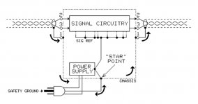
Also, a "star grounding" doesn't necessarily have to be a rats nest of wires. It could be as simple as something like this.
Proper Internal Grounding Avoids Ground Noise Coupling
http://www.jensen-transformers.com/as/as085.pdf
The "rats nest spider" of wires some people still do is more like a carry over from the era of vacuum tube point to point wiring.
Attachments
Also recommend his book "The fields of electronics"
Yes, it's available for free here:
The Fields Of Electronics - Understanding Electronics Using Basic Physics - R. Morrison (Wiley, 2002) WW — Free Science Library
Also, a "star grounding" doesn't necessarily have to be a rats nest of wires. It could be as simple as something like this. The "rats nest spider" of wires some people still do is more like a carry over from the era of vacuum tube point to point wiring.
Yes, exactly. That approach is just no longer suitable for modern circuitry.
It becomes a case of those that want to believe in good wiring practice and those that blindly "star ground" without thinking about the routes that the currents are forced to follow by tortuous wiring errors.
So star ground is not the way to go on a preamp then. I don't have a 2 sided board with a ground plane yet. I'm sure that is the better way but for now I am trying to understand how to make what I have as quiet as I can.
I understand now the importance of tightly twisting sends with returns but as far as grounding points... Do you think the method in this picture separating power from signal grounds that Zero D suggested is the best bet then?
Attachments
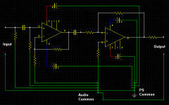
Do you think the method in this picture separating power from signal grounds that Zero D suggested is the best bet then?
The bypass capacitors must form a very small loop at the amplifier to be effective. Long traces to "ground" make them useless.
The pcb layout must be arranged to reflect this.
Last edited:
This simple current analysis shows us:
1. Where the current loops are for PCB design.
2. That this is an inverting amp.
3. Problem with the speaker/load return.
4. Missing PSU connections.
1. Where the current loops are for PCB design.
2. That this is an inverting amp.
3. Problem with the speaker/load return.
4. Missing PSU connections.
Attachments
Last edited:
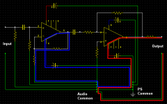
post74 is a disaster.
It uses star ground without thinking about what route the return current is being forced to follow.
Post76 shows two of these return routes.
Simply marking them on a printed copy of the schematic using coloured crayons SHOWS the LOOP AREAS that are being forced upon the Two Wire Signal connections.
It uses star ground without thinking about what route the return current is being forced to follow.
Post76 shows two of these return routes.
Simply marking them on a printed copy of the schematic using coloured crayons SHOWS the LOOP AREAS that are being forced upon the Two Wire Signal connections.
start by drawing the Flow ROUTE from the Source into the Receiver.
Then draw on the Return Route that MINIMISES the Loop Area, all the way back to the Source.
Then Build in that two wire connection.
Proceed to the next two wire connection.
When all the signal connections have been completed, each with their own two wire close coupled (and where possible twisted) connections, you will find that a few, very few, extra voltage reference connections are required. One such is the Signal Return to Speaker Return.
post74 is a disaster.
It uses star ground without thinking about what route the return current is being forced to follow.
Hahaha, yeah I think I am starting to understand now. Does this mean that most schematics will not show things being close coupled?
This simple current analysis shows us:
1. Where the current loops are for PCB design.
2. That this is an inverting amp.
3. Problem with the speaker/load return.
4. Missing PSU connections.
Yikes. Do you have a schematic handy that shows proper routing for minimizing loop area? I don't care what kind of circuit it is, I'm only curious what that kind of a schematic would look like.
- Status
- Not open for further replies.
- Home
- Source & Line
- Analog Line Level
- Which one of these wiring schemes will have lower noise?