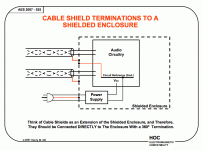
1. There must be one, and only one, ground connection point to the metal chassis
This the Main Audio Ground (MAG) only applies to DC power supply and audio circuit common.
Not to shields or the AC Safety Ground/Protective Earth.
*************************
While some finished Class II components must not have their chassis grounded. (they are doing trick power supplies - think Bob Carver).
But if you are using a stand alone Class II power supply, as is more and more common that warning doesn't apply.
*******************
Three types of chassis connections:
a] AC Safety Ground/Protective Earth.
b] Main Audio Ground (MAG).
c] Shield only - like the XLR pin1.
Note that the Main Audio Ground (MAG) should connect to the chassis near the Input/Output jacks.
If there is current on the interconnect shield, then the building may have an AC power system wiring error. (maybe a Neutral and Ground swap)
I had my X-Altra pre measured on an AP when I was living in Japan. The mains noise levels with the inputs shorted are at about -110 dB ref 0 dBV. You can see the measurements in the X-Altra write up.
-110dB at reference?!! That is ridiculously quiet! I'm guessing that wasn't some A-weighted cheat code spec either. The way things have been going for me lately, I would jump for joy if I could get -95dB. Thanks Bonsai, I'll let you know how it turns out. 🙂
If there is current on the interconnect shield, then the building may have an AC power system wiring error. (maybe a Neutral and Ground swap)
Correct - you should not have current in the shield (XLR or single ended).
However, the use of SMPSU's in a lot of gear (e.g. CD players like my Pioneer SACD) cause ground loop problems and HF noise
This is also why I recommend one chassis ground point. If you do have current flowing along the shield and you have multiple chassis ground points, you can get additional noise.
Hi, i posted a screenie in Post # 28 here http://www.diyaudio.com/forums/anal...anding-source-return-current-flow-pcbs-3.html which shows how i achieve low noise & hum
Not necessary...............Note that the Main Audio Ground (MAG) should connect to the chassis near the Input/Output jacks.
Simply connecting to the Chassis with a low impedance wire is good enough.
A long wire to a remote location will have inherently higher impedance and the higher impedance makes a worse connection to the enclosing metal screen.
The shield (not the signal return which is inside the shield) is very likely to have current flowing in it.Correct - you should not have current in the shield (XLR or single ended). ...........
H.Ott tells us why and goes on to tell us that the shield should be chosen to have low resistance.
This applies especially for a shield between separate pieces of metal enclosed chassis, but also applies to the shield around internal wiring protected by an enclosing chassis.
Joffe's paper that I linked a few days ago shows WHY the current flows and HOW to reduce that current.
page21
Page22 gives a number of solutions for reducing the shield currents or reducing the voltages generated by the shield currents.
It NEVER claims to eliminate the shield current.
Page36 shows how NOT to and HOW TO terminate the shield.
Surely that means there ARE shield currents !!!!WHAT CAUSES SHIELD CURRENTS
Differences in Ground Potential
Magnetic Field Induction
Radio Frequency Pickup
Page22 gives a number of solutions for reducing the shield currents or reducing the voltages generated by the shield currents.
It NEVER claims to eliminate the shield current.
Page36 shows how NOT to and HOW TO terminate the shield.
Last edited:
I would like to think that the only shield current in a correctly set up system should be the signal return current. That there are mains currents circulating through the shield attests to the fact that wiring, and specifically grounding, on the mains side leaves a lot to be desired and this is where initial efforts should be deployed to resolve noise problems.
Often you get ground potentials between the equipment chassis via induction and the earth connection is primarily via the shield and not the ground (ie earth) wires on the mains plugs. This of course causes noise. It is for this reason for example that on power amplifiers I separate the signal ground from the main amplifier ground with a 15 to 22 ohm resistor. The main amplifier ground is then connected to the chassis directly, or through a GL (ground lifter), and the chassis bonded to other equipment chassis through the mains earth connection. This system works well on double insulated gear as well.
As a first step in reducing, or stopping shield currents, I would use the same mains outlet and earth connection between my pre, CD player and power amp. All the equipment earths are then starred off one earth. Of course in a professional environment, this is often not possible, so balanced connections and isolating transformers have to be applied.
GL's can also work wonders is used appropriately since the voltage potential between equipment grounds is often only a few 10's to a few 100's of mV.
Last edited:
For RFI, connect a 1nF ceramic cap directly from the input connector ground to the chassis right next to the connector. Use RFI filters on the input circuit of your amp as well. Both these techniques work very well.
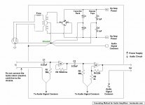
I work with mic level input signals all the time. This is how I do my wiring.
IEC AC Ground - this is the safety ground, connect to metal case immediately, right near the IEC AC inlet.
Transformer Center-tap - connect to PSU PCB.
PSU output ground - connect to preamp board
Audio Input and Output XLR jacks - connect ground (pin1) via wire to preamp PCB.
Audio Input and Output XLR jacks - also, short pin1 to metal body case of XLR jacks, which is then screwed to the metal case, and making electrical contact with the case... effectively grounding the case
Any noise coming externally via the input or output XLR jacks are immediately shunted to ground/metal case right at the entrance.
The only "wire" I have connected to the metal case is the safety ground from the IEC AC inlet connector.
This scheme has proven to be very quiet, even with the input signal amplified to 72dB gain (4000x amplification).
Bonus: Use a toroid transformer, and rotate toroid a few degrees left or right to find the sweet spot where hum/noise is the minimum. (of course, unit is powered on and you're listening to the output noise via a connected speaker). Once the sweet spot is found, turn off power and tighten bolt on toroid transformer.
My post #8, but this picture explains it better. Thanks for the pdf Marce.
Reading Bill Whitlock's numerous papers on grounding explains it in detail.
Attachments
My input is RCA and output is XLR. 00940, is there anything wrong with these updated pictures now?
Yes you have labelled the required 7915 regulator in the V- supply rail as a 7815
I would like to think that the only shield current in a correctly set up system should be the signal return current. That there are mains currents circulating through the shield attests to the fact that wiring, and specifically grounding, on the mains side leaves a lot to be desired and this is where initial efforts should be deployed to resolve noise problems.
Often you get ground potentials between the equipment chassis via induction and the earth connection is primarily via the shield and not the ground (ie earth) wires on the mains plugs. This of course causes noise. It is for this reason for example that on power amplifiers I separate the signal ground from the main amplifier ground with a 15 to 22 ohm resistor. The main amplifier ground is then connected to the chassis directly, or through a GL (ground lifter), and the chassis bonded to other equipment chassis through the mains earth connection. This system works well on double insulated gear as well.
This is why Hennry Ott recommends a low resistance shield, its not that the grounding is wrong as such, sometimes the low frequencies can find a lower resistance route via the mains earth wiring. Using a cable with a good low resistance shield helps minimise or avoid this problem.
I have seen ground loop problems on equipment that will never be fastened to the mains earth pin, even more fun, but it does show that these problems can plague anyone, its a problem lurking in the background waiting to bite you.
These sort of problems don't only plague audio. other system suffer from ground loops; in fact its better to rephrase the problem, all equipment has ground loops it is controlling these loops and keeping grounds at the same potential (thus avoiding ground currents flowing in unsuspected wiring and causing noise) that is the aim. 🙂
Some more interesting views on interference free audio systems...
Tony Waldron's EMC ranting and ravings
Jneutrons gallery also has some nice diagrams.
Balanced signal distribution helps, even better is balanced signalling with fully differential signals (balanced audio).
The 15~22 Ohm resistor I mentioned forces the ground loop currents to flow through the earth connection between the equipment.
All my gear is EARTHED so its 100% safe.
The signal and safety earth ground, coupled to the ground lifter give me great results.
All my gear is EARTHED so its 100% safe.
The signal and safety earth ground, coupled to the ground lifter give me great results.
Last edited:
.
I think it's good to remember that chip amps are supposed to be simple. That's their reason for existence in the first place. You're not supposed to need an engineering degree. You don't even need a high school diploma.
Grounding for chip amp circuits carries through with the "simple" principle. The rule is don't mix the audio signal with any other. Observe that rule and you're home free.
A nicety is to subdivide the power supply circuit. The sacrosanct audio signal is always itself only, while the power circuit can be subdivided into: 1. The capacitor bank (smoothing capacitors) in the power supply. 2. The bypass capacitors in the power supply. 3. The decoupling capacitors at each op amp (if used, and they should be).
This is not hard, and not complicated. As the circuit diagram below shows, it simply means running conductors from what should be called "commons" (instead of "grounds") to the single ground point. These conductors were going to be there anyway, but now they're connected in an organized manner. All with the goal of keeping the audio signal away from power lines.
(Decoupling capacitor ground conductors are not shown in the circuit diagram for the sake of simplicity, these are run directly to the ground point.)
But what about the ground point, where everything does come together? This is the center or neutral terminal of the power transformer, and as a matter of fact this point is a horror story of spikes, harmonics, AC riding on DC carriers, currents flowing in several directions at once, and generally it's not the sort of place where a nice audio signal should go.
But happily this hell on earth (for audio signals) is brought into good order by the influence of the transformer itself. The transformer's relatively enormous magnetic field and current flows are so big that the various distortions are dwarfed by comparison. They're still there, but they're so relatively small that they become insignificant. The engineering term for this is "swamping effect." If you want to understand exactly how it works you will have to get that engineering degree, and going for a doctorate might be wise.
But if you can accept the obvious, then the rule is don't mix the audio signal with any other. Except at the ground point.
.
Attachments
It seems rather strange to me joining everything together at one of the noisiest points of the circuit. Myself I would be tempted to have a loop for the incoming a.c. to the smoothing capacitors, then have a point tee'd of there for the star point where there are less circulating currents such as a.c. ripple and diode switching noise...
Again local decoupling caps are not a lot of use at the end of long traces, maybe this is why ALL data sheets recommend them near to the device pins to MINIMISE loops.
Again local decoupling caps are not a lot of use at the end of long traces, maybe this is why ALL data sheets recommend them near to the device pins to MINIMISE loops.
You should explain you reasoning - it's the only way we can get a discussion and learn that way.
- Status
- Not open for further replies.
- Home
- Source & Line
- Analog Line Level
- Which one of these wiring schemes will have lower noise?