Hahaha, yeah I think I am starting to understand now. Does this mean that most schematics will not show things being close coupled?
Yes, a schematic diagram is just for showing what is connected to what, and has little relation to most physical circuit layouts.
For clarity, most schematics have signal flow shown from left to right, and voltages more positive higher.
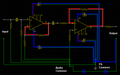
Loop area and Power routing are not the only problems. Inductance is also a problem that should be identified. Feedback loops and bypass capacitors must have short traces to the opamps and ground. The datasheets give plenty of info on this. This part of the layout is critical for stability and low distortion of the circuit.
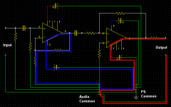
Schematic 1: Loops
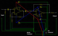
Schematic 2: Power connections
Schematic 3: parasitics/inductance
Schematic 1: Loops
Schematic 2: Power connections
Schematic 3: parasitics/inductance
Attachments
. . . Now you know why I put a 22 Ohm resistor in series with the decoupling cap in each opamp supply rail in my preamps. The resistors and decouple caps are located right at the opamps, and I use a dedicated 'dirty' ground return.
.
<< I have read things so far that discuss different parts of a circuit as being "upstream" and describing a river that flows from low current into higher currents. >>
Upstream and downstream refer to the direction of current flow, current quantity doesn't enter in. It can also refer to the progression of the audio (or any) signal through a circuit, from input to output.
For instance, the audio signal flows "downstream" from the input to the output. A power supply terminal is upstream of everything connected to it.
Do not make this complicated because up/down stream always refers to one point only, and you say things are up- or downstream of that point. It's just a convenient way of referring to things, it's not a law of physics.
Shredhead, it's painfully obvious that you have no clue. For one thing, you don't realize that the grounding method in your post #61 is the same one I gave you in post #57.
More importantly, you don't realize that all this advice you're getting is variations on the basic theme of "don't mix audio signal voltages with power supply voltages." It's not that everybody has a different theory on grounding, it's that everybody is telling you the same thing in different words, but you're not getting that (Sometimes they don't get it either, but that's a different story).
Look at the people who've told you "I did such-and-such and the amp is dead quiet." And yet they all did a different such-and-such. Should this not tell you something?
It should tell you that there is no "best way." It might also suggest that you don't need one.
Manufacturers sell these chips worldwide, by the tens of millions. This means the customer-engineers they deal with are not always MIT graduates. In fact, some of them have questionable credentials, like nobody's ever seen their high school diploma.
To deal with this situation the factory makes their chips bulletproof, not to say idiot proof. This being so, you do not--not--need to go through all this, and about all that's going to result is getting yourself confused. If you don't know Ohm's law, trying to discuss circuit niceties is just not going to lead to anything good.
For crying out loud, stick with the NE5532, the LM1875, or the LM3886. These chips will serve you well for anything short of a stadium PA system, and they're tried and proven by tens out thousands of guys who don't know one end of a soldering iron from the other, at least until it's plugged in. Chip amps are not supposed to be complicated, and if you make them that way it won't help anything.
Oh and by the way, just to add to your misery, shielding and circuit grounding are two different things, they have nothing to do with each other.
I keep checking this thread because it's like the proverbial train wreck, you can't look away.
.
Last edited:
My screenies that are being used are from here in Post # 28 http://www.diyaudio.com/forums/anal...anding-source-return-current-flow-pcbs-3.html
That's what i showed in the above screenie !
Originally Posted by Bonsai
The resistors and decouple caps are located right at the opamps, and I use a dedicated 'dirty' ground return.
That's what i showed in the above screenie !
.Shredhead, it's painfully obvious that you have no clue. For one thing, you don't realize that the grounding method in your post #61 is the same one I gave you in post #57.
Oh and by the way, just to add to your misery, shielding and circuit grounding are two different things, they have nothing to do with each other.
I keep checking this thread because it's like the proverbial train wreck, you can't look away.
.
Mr. Bentsnake, what you've just said... is one of the most insanely idiotic things I've ever heard. At no point in your rambling incoherent response were you even close to anything that could be considered a rational thought. Everyone in this room is now dumber for having listened to it. I award you no points and may God have mercy on your soul.
Seriously though stay out of my thread, you obviously have nothing useful to contribute. Go start your own, you can call it "I $hit on people who are using this forum as a resource to learn". It should be a lot of fun for everyone. 😉
Shred,
don't take it too hard.
Many of Bents post ramble on and
don't take it too hard.
Many of Bents post ramble on and
Read some that were not directed at you and see the pattern.have nothing useful to contribute.
. . . Now you know why I put a 22 Ohm resistor in series with the decoupling cap in each opamp supply rail in my preamps. The resistors and decouple caps are located right at the opamps, and I use a dedicated 'dirty' ground return.
I understand the dedicated dirty return but what does the 22 Ohm R do? Is that an RC filter?
I understand the dedicated dirty return but what does the 22 Ohm R do? Is that an RC filter?
It lowers the Q of the resonance.
1r0 may be enough
you might find that 0r1 to 0r5 is enough to lower the Q so much that ringing (due to L & C) is snubbed.
This is where ultra low ESR does not help.
Don't use film caps for decoupling, their ESR is too low to snub the ringing.
It turns out that the higher ESR of an X7R capacitor is just about ideal.
you might find that 0r1 to 0r5 is enough to lower the Q so much that ringing (due to L & C) is snubbed.
This is where ultra low ESR does not help.
Don't use film caps for decoupling, their ESR is too low to snub the ringing.
It turns out that the higher ESR of an X7R capacitor is just about ideal.
X7R small cases (low impedance) relatively high value, lossy to an extent, best caps for decoupling next to an IC, used in their billions...
This is where ultra low ESR does not help.
Don't use film caps for decoupling, their ESR is too low to snub the ringing.
It turns out that the higher ESR of an X7R capacitor is just about ideal.
In some of their CD players, Phillips used 10 Ohm resistors in the traces to the op amps.
Older designs I would presume....
Its often good practice these days to isolate the power for different circuit blocks with a ferrite based Pi filter, or even an inductor for slower speed stuff.
Its often good practice these days to isolate the power for different circuit blocks with a ferrite based Pi filter, or even an inductor for slower speed stuff.
In some of their CD players, Phillips used 10 Ohm resistors in the traces to the op amps.
In the cd723 opamp PS lines, 220R followed by 220uF. For the tda1545 in the same player, 100R followed by 220uF in parallel with 22n. Noise filtering rather than worries about resonances I'd say.
Does anyone know what the formula is that they are using to determine the R and cap values? Is it as easy as the RC high pass filter formula or is it something completely different for resonance? I would imagine if it was to limit the resonance it would always be centered at 60Hz since (for my projects at least) this seems to be the highest peak in the noise floor.
I understand the dedicated dirty return but what does the 22 Ohm R do? Is that an RC filter?
1. Provides HF roll off to attenuate regulator noise in conjunction with the 100 uF cap to ground
2. Heavily damps the supply rails, preventing ringing
3. Isolates the amplifier stages from each other and keeps supply currents in a relatively tight loop around the decoupled stage(s)
It is a method that will improve the voltage stability at the opamps.
You could go as far as giving each opamp its own voltage regulators if you wanted to.
It does not help with noise from ground loops!!!!
You could go as far as giving each opamp its own voltage regulators if you wanted to.
It does not help with noise from ground loops!!!!
Thanks everyone!
My project is finished and it is the most quiet thing I've put together to date. Thank you all so very much for the help. I've been plagued with noise problems in the past with EQ's that I've built due to messy and improper wiring techniques and it is so frustrating. Now I am finally coming to understand close coupling flow and returns, keeping loops as short as possible and the up and downstreams of ground currents.
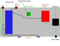
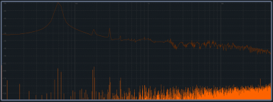
This is a basic diagram of how I wired this unit. The input jack is isolated from the chassis and the ground from it goes to the preamp PCB's ground point where all the signal grounds are kept. The XLR's pin 1 is connected to ground at the chassis right where it comes in and no where else. The star ground is the only other point where the ground has connection to the chassis. The op amps power pin's bypass caps are traveling back to the star ground near the PSU and away from the signal ground point. There was a bit more going on in reality but this is a simplified representation that I hope will help someone reading. I also included a pic of the noise floor of my project. I have an Asus Essence STX soundcard that is pretty darned quiet and when I put my project in the loop, not only does it not add to my soundcard's noise floor but it actually lowers it by about half a dB. I'm guessing because of the CMRR? Either way, I'm not complaining a bit.
Thanks again, big thumbs up to all who helped me!
My project is finished and it is the most quiet thing I've put together to date. Thank you all so very much for the help. I've been plagued with noise problems in the past with EQ's that I've built due to messy and improper wiring techniques and it is so frustrating. Now I am finally coming to understand close coupling flow and returns, keeping loops as short as possible and the up and downstreams of ground currents.
This is a basic diagram of how I wired this unit. The input jack is isolated from the chassis and the ground from it goes to the preamp PCB's ground point where all the signal grounds are kept. The XLR's pin 1 is connected to ground at the chassis right where it comes in and no where else. The star ground is the only other point where the ground has connection to the chassis. The op amps power pin's bypass caps are traveling back to the star ground near the PSU and away from the signal ground point. There was a bit more going on in reality but this is a simplified representation that I hope will help someone reading. I also included a pic of the noise floor of my project. I have an Asus Essence STX soundcard that is pretty darned quiet and when I put my project in the loop, not only does it not add to my soundcard's noise floor but it actually lowers it by about half a dB. I'm guessing because of the CMRR? Either way, I'm not complaining a bit.
Thanks again, big thumbs up to all who helped me!
Attachments
Last edited:
- Status
- Not open for further replies.
- Home
- Source & Line
- Analog Line Level
- Which one of these wiring schemes will have lower noise?