It will have continuity on/from the preamp board. Out GND should be taken from the output circuit of the preamp.
Gajanan Phadte
In what way do you mean that it would be isolated?
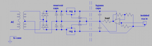
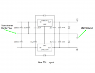
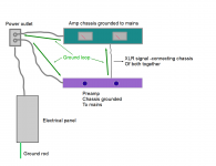
The attached scheme has worked well for me. It's much easier to think in terms of "ground bus" than to try to achieve a perfect star ground, which often leads to complicate wiring for little benefits. In any case, the center tap of the transformer goes to the ground terminals of the reservoir caps and nothing else.
It is not quite clear from reading the thread if you're going to use unbalanced or unbalanced signal (rca or xlr)... the first pics show a unbalanced config but I see references to xlr afterwards ?
I see no reason not to attach earth to the case, right at the entry point. Then, either connect a thick wire from that point to the rca gnd or insert a groundloop breaker in between the earthed case and the audio common.
Attachments
Henry Ott, excellent info on grounding....
home page
As to safety earth, devices that are not grounded are double isolated, as a DIYer you do not have the tools or testing facilities to do double isolated. Further I am sorry to inform you that it is a requirement in all countries to follow safe practices when doing mains related work and not having a protective earth connection is dangerous, and discussing such designs I believe is against this forums rules.
Last edited:
The sad reality being that many if not most outlets in older European houses are not connected to earth. Even if earthing the case is something which should always be done, it should be complemented by extra attention to mains wiring.
Everyone can save their breath about grounding. The transformer I bought is double insulated so what I'm doing is legal as $hit. Please start your own thread if you wish to discuss it further because I really don't.
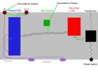
My input is RCA and output is XLR. 00940, is there anything wrong with these updated pictures now?
I changed where the transformer's center tap is going and connected the in's ground to the out. The only way that they now have continuity with the rest of the circuit is through the chassis now. Is this right? What about the location of the power rails wire?
Is connecting the input ground to the output a technique to keep noise to a minimum or does it avoid ground loops somehow?
I have read that having 2 star grounds is beneficial. One for bypass caps and PSU stuff and another for signal grounds. Is this true?
What location of ground wires should I avoid to eliminate ground loops?
Attachments
Last edited:
My understanding of double insulated is that the chassis is not connected to ground, including the PSU or audio ground.
If anyone is interested in the dangers of the shredhead method of grounding, Google 'musician electrocuted'
If anyone is interested in the dangers of the shredhead method of grounding, Google 'musician electrocuted'
Last edited:
If anyone is interested in the dangers of the shredhead method of grounding, Google 'musician electrocuted'
The shredhead way? Thanks for insult there Mark.
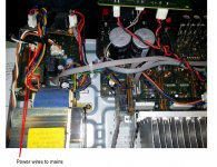
This is a picture of a Sony receiver that I recently repaired. Note the power wires coming in from the mains. There is NO GROUND PLUG on the power cord for this 100W per channel 5.1 AVR. Looks like it's the SONY way to do things too!
This is perfectly legal in the USA. I understand that everywhere else in the world has different rules/voltages than here and I'm not advising you guys out there how you should do things. Stop wasting my time about this and if you have no information to add to this thread about what the thread is about then start your own.
Attachments
Well, you don't need that green star gnd anymore.
It's best to isolate the input rca from the chassis. From the rca, both signal and gnd line goes to the preamp pcb. On the pcb, the gnd of the input and the gnd of the power supply should be connected together. It becomes a matter of pcb design. What are you using as preamp btw ?
If you have xlr output, which means a balanced line, then your "gnd" output isn't really gnd but shield. This shield (pin1 on the xlr) should be connected to the case directly. In which case, it would be best to also earth your preamp, not only on safety grounds but to make shielding more efficient. You never know how the receiving end will be wired...
And since it's best not let your shield float wrt to your preamp balanced outputs, your "audio gnd" should be somehow linked to the output xlr pin1 (and thus earth). I would implement a ground loop breaker as in the fig.4 of this article . The groundloop breaker would go in between the case and the gnd output of the power supply.
If you have xlr output, which means a balanced line, then your "gnd" output isn't really gnd but shield. This shield (pin1 on the xlr) should be connected to the case directly. In which case, it would be best to also earth your preamp, not only on safety grounds but to make shielding more efficient. You never know how the receiving end will be wired...
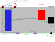
I know that my amp has continuity between the mains safety ground, the chassis and pin 1 on the XLR input. Now see my pic...
I have done it this way in the past and I get noise from the ground loop. Especially if this loop forms itself around other magnetic fields from the transformers of other equipment around.
I just don't understand how this can be the best way. I understand that you would attempt to correct that with a ground loop breaker (transformer) but isn't there a better way to wire up a preamp so you don't have to use that?
Attachments
Are you mixing unbalanced and balanced lines connecting your different equipment?
Did you make special cables to connect them together?
See this
Sound System Interconnection
Did you make special cables to connect them together?
See this
Sound System Interconnection
The problem is all local, you can ignore the electrical panel. It is very difficult to say what happened to your earlier configuration not knowing how both the preamp and the amp were internally wired. The problem can also involve the source in front of the preamp. Did you try to connect the shield only at one end ?
It's not me saying it's the best way. See for example: Sound System Interconnection or http://www.diyaudio.com/forums/diya...udio-component-grounding-interconnection.html for more details.
The groundloop breaker isn't a transformer, it's just a few passive parts. Although an half decent transformer from edcor would make things a lot easier. ;-)
Are you mixing unbalanced and balanced lines connecting your different equipment?
Did you make special cables to connect them together?
I am taking unbalanced RCA input and after the preamp circuit, it goes to a balanced line transmitter circuit to send XLR out of the preamp. No special cables needed in this case.
Although an half decent transformer from edcor would make things a lot easier. ;-)
Thanks for your help 009, I'll read that. I would really prefer to understand how to avoid problems in the design if I am able.

Look at the loop created by the signal in, better that is twisted pair to the Pre-amp PCB. Everything sums at that point, the input return is going to have to go through there and with all the currents flowing through there its probably going to be at a slightly higher potential. So if the input signal and its return form the smallest loop as a twisted pair to the pre-amp board, you minimise their loop area (and thus susceptibility to noise pick up) and minimise the returns added parasitics and avoid a possible area of high current density and thus possibly at a higher potential than other "grounds" or designated 0V's
An AES presentation that covers a lot of what your asking,:
http://www.hottconsultants.com/pdf_files/aes-2007.pdf
An AES presentation that covers a lot of what your asking,:
http://www.hottconsultants.com/pdf_files/aes-2007.pdf
Last edited:
Try it. That's what I described in my post #8.
... just missing the safety ground from the IEC AC inlet, connected to chassis 🙂
... just missing the safety ground from the IEC AC inlet, connected to chassis 🙂
Shredhead
1. There must be one, and only one, ground connection point to the metal chassis
2. The ground connections of input connectors, output connectors, headphone socket if any, pot wipers etc must not connect to the chassis (XLR is a special case - see later)
3. Strictly follow star ground to 'T' wiring practice to avoid common impedance coupling
4. Finally, you can use a ground lifter between you chassis and your electronic star ground. I recommend a 25 A bridge rectifier. One AC end goes to the star ground on your PCB, the other to the single ground point on the chassis. Connect the + and the - on the rectifier. Your incoming mains ground connection must go directly to the same point where your ground lifter attaches to the chassis - i.e you still obey the one connection point to the chassis rule.
XLR: connect the ground wire to the chassis. Make sure however that there are no ground loops flowing through the XLR outer screen. You can just measure the current with an AC mA meter. If you are getting current flow, you have an earth loop between the equipment - check your grounding.
If I find time, I'll add a 'how to wire up a preamp' doc on my website.
I can attest that both my Symphony and my X-Altra mini preamplifier are dead quiet.
I had my X-Altra pre measured on an AP when I was living in Japan. The mains noise levels with the inputs shorted are at about -110 dB ref 0 dBV. You can see the measurements in the X-Altra write up.
- Status
- Not open for further replies.
- Home
- Source & Line
- Analog Line Level
- Which one of these wiring schemes will have lower noise?