I have an Iron Pre 2021 version. I've got the voltage set to +-15V. Easy enough. I'm not using the relays, I just want one input RCA connection and one output RCA connection.
How do I wire in an Alps blue velvet 50K pot? I've got as connections-
CWL (Clockwise Left)
WiperL (Wiper Left)
CCWL (Counterclockwise Left)
CWR
WiperR
CCWR
As a guess-
CW is in to the pot.
Wiper is out from the pot.
CCW is ground from the pot
Do I have that correct?
How do I wire in an Alps blue velvet 50K pot? I've got as connections-
CWL (Clockwise Left)
WiperL (Wiper Left)
CCWL (Counterclockwise Left)
CWR
WiperR
CCWR
As a guess-
CW is in to the pot.
Wiper is out from the pot.
CCW is ground from the pot
Do I have that correct?
Yep you've got it.
I can't remember if I sent you boards or not. There were a few versions of '2021' boards. I had two versions, and Jim had at least one more. Either way, I think the notations for the pots are all the same. I've noted the corresponding "older" notations for cross reference. I'm assuming you're building SE since you note R and L vs. + and -.
On some older boards they were labeled exactly as you noted.
Input (CW)
Output (Wiper)
Ground (CCW)
I admit to liking the older notation a bit better... but I completely understand the change. It's noting the pin that has the lowest resistance to the wiper when the pot is turned fully to that direction (or at least I think that's the logic). I have to beep it out either way b/c I get confused far too easily.
On the pot => 2 rows of 3 pins. Doesn't matter which row you pick as left or right.
Triple check my work. The resistance between the pin I've noted as CW (input) and the wiper (output) should be at its highest with the pot turned all the way CCW (lowest volume / most attenuation from in to out).
Note that if you follow the schematic (and traces) that the both CCW pads go straight to ground. CW pads go to the input selection relays. The wipers run straight to the "input section" of the circuit.
If you flip the pot over with pins pointing up and shaft pointing toward you ... it's like this. I didn't have a two gang pot within reach, but it should be the same thing...
If you're unsure how to do it without the relays, check your schematic. If still unsure, ask the mighty ZM.
Enjoy! I love this pre-amp!
Edited to add - Or the logic could be that when the pot is oriented "right side up", the shaft rotates 'toward' that pin... when rotating the pot CW, it turns toward the CW pin. DOH! Like I said, I'm a bit slow. Still, DMMs are my friend.
Attachments

Last edited:
I have an Iron Pre 2021 version. I've got the voltage set to +-15V. Easy enough. I'm not using the relays, I just want one input RCA connection and one output RCA connection.
How do I wire in an Alps blue velvet 50K pot? I've got as connections-
CWL (Clockwise Left)
WiperL (Wiper Left)
CCWL (Counterclockwise Left)
CWR
WiperR
CCWR
As a guess-
CW is in to the pot.
Wiper is out from the pot.
CCW is ground from the pot
Do I have that correct?
when looking at pot from shaft side, pins down
CCW is most left
Viper is mid
CW is most right
now - just one input - connect hot from RCA to CW on pot itself
solder Viper and CCW to appropriate pads at pcb
route GND from handy GND pcb pad, or from CCW pad on pcb to RCA GND
simple as that ....... of course, same applies for both channels
or............ you can accordingly solder pot to pcbs pads (all 3 +3) , solder wires from RCA to appropriate input pads on pcb, and short appropriate relay pads
that would be, without invoking graphical illustration, relay pad close to input pad with inside pad on same side; ignore mid relay pads, they are left floating
Thank you both, IAIMH and ZM for the help. I appreciate it. I don't think I would figured it out on my own.
IAIMH, I think my board's path was ZM to 6L6 to a fellow member.
IAIMH, I think my board's path was ZM to 6L6 to a fellow member.
Hi, I’m trying to find some info on the different way to wire the autoformer to have different gain settings. Is there any other ways to wire it other than the 6db and 12db like in the iron pre. Let’s say to have 0, 3 or 9 db of gain? I’m don’t think that I fully understand the two wiring diagram here.. 😅
Attachments
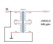
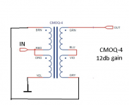
with these transformers, there is no other way
you can use Edcor 600:15K to get higher gain
600:15K (nominally) will give 6V/V (15db5) in autoformer arrangement
in this moment ( Flue) better to wait, I can't check is there center tap on 600:15K , allowing even higher gain
you can use Edcor 600:15K to get higher gain
600:15K (nominally) will give 6V/V (15db5) in autoformer arrangement
in this moment ( Flue) better to wait, I can't check is there center tap on 600:15K , allowing even higher gain
Im using the cinemag. It was just out of curiosity not that I need more gain. Thank you ZM.
Since I will only have two sets of inputs, I’m planning to use one of the three remaining relay to switch between 6 an 12db of gain. Is it a bad idea? Any problem that I could ran into with the relay circuitry / relay psu to energize more than one relay at a time?
Since I will only have two sets of inputs, I’m planning to use one of the three remaining relay to switch between 6 an 12db of gain. Is it a bad idea? Any problem that I could ran into with the relay circuitry / relay psu to energize more than one relay at a time?

For the iron pre, can it be built without volume control and with only a single input? I was planning to do volume control and source switching upstream.
Good idea.Yes ironpre se. I think I’m good, not too complicated. I will begin by making it work properly as is than will add the switching. Thank you again
I can't tell you how many times I've popped the lid to switch the gain setting jumper. I guess I haven't been bothered enough yet to wire a proper switch on the front panel....Just Lazynessss

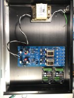
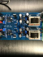
Progress, finally received the chassis. I’ve hooked up the iron pre to the transfo. Everything seem to be ok, +15v -15v and offsets easily adjusted.
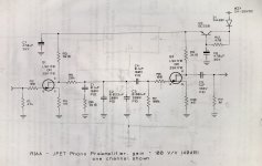
I have some riaa filter board that I want to add. So question for ZM, would it be detrimental to the good Gemini to hook up my riaa boards to the V+. Pretty simple design, 2x2sk170 + cap multiplier per channel. I’ve included a schematic bellow.
Hubert
I have some riaa filter board that I want to add. So question for ZM, would it be detrimental to the good Gemini to hook up my riaa boards to the V+. Pretty simple design, 2x2sk170 + cap multiplier per channel. I’ve included a schematic bellow.
Hubert
Attachments
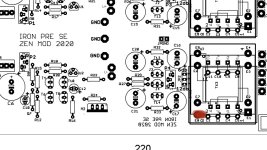
So.. first test show no gain at the 6db setting and 6db gain at the 12db setting.. Realized that I must have mounted the transformers the wrong way. Can someone double confirm this for me before I pull them out? Pin one on the cinemag should be where the red dot is.
Edit: pretty obvious that they are reversed. Output at buffer is unity so it’s good. Working on it
Edit: pretty obvious that they are reversed. Output at buffer is unity so it’s good. Working on it
Attachments

Last edited:
if you mounted them backwards ....... that's possible only if using some force
pins 1&2 are having smaller pitch than other pins, so practically pin1 being key
final iteration of pcbs ( that going to Store) is having revised pads for xformers, so no more need to cut corner pins of Cinemags
pins 1&2 are having smaller pitch than other pins, so practically pin1 being key
final iteration of pcbs ( that going to Store) is having revised pads for xformers, so no more need to cut corner pins of Cinemags
Ok everything is good it’s playing music! My pin 1 was cut for a previous project and with the board revision that I have it was an easy mistake. Totally my fault. Also found that I needed to tie pin 5 and 8 to have proper output. Rhthatcher made the exact same mistake in 2020 😅
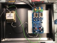
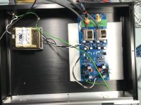
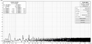
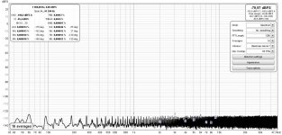
Now it’s performing up to standard. I had left the power transformer sitting on a foam to optimise radiated noise and now I have reached the limit of my soundcard 😉 Left you can see the noise picked up with the transformer mounted pointing vertically and right with the transformer pointing at the cinemag. And I must say that it sound really good so far. Thank you ZM
Now it’s performing up to standard. I had left the power transformer sitting on a foam to optimise radiated noise and now I have reached the limit of my soundcard 😉 Left you can see the noise picked up with the transformer mounted pointing vertically and right with the transformer pointing at the cinemag. And I must say that it sound really good so far. Thank you ZM
Attachments
- Home
- Amplifiers
- Pass Labs
- What's wrong with the kiss, boy?