signal wire - tiniest, not screened, solid core if you're not allergic
when using fatter wire, especially screened, you're killing it
I'm using some older dunnowhichbutknownbrand 0.2mm Dia silvered solid core copper, with some non-melting isolation
there is a ton around so called Kynar isolated solid core silvered wire, either 0.2 or 0.25mm Dia
mains- put IEC most left you can, route mains wires under the base plate near left side plate; that way is no shielding needed
I'm usually placing mains switch above IEC on back plate, if not using IEC with incorporated switch
one M4 screw near IEC placed on base plate- holding all Safety GND leads, each wire having eyelet on end
Last edited:
WOW! Looking good!!!
Coming from the "chassis master" - I am honored 😀
signal wire - tiniest, not screened, solid core if you're not allergic
Should be no worry.
when using fatter wire, especially screened, you're killing it
I never knew that. More to learn.
I'm using some older dunnowhichbutknownbrand 0.2mm Dia silvered solid core copper, with some non-melting isolation
there is a ton around so called Kynar isolated solid core silvered wire, either 0.2 or 0.25mm Dia
I did not find any of the Kynar branded insulation, but I did a search for solid copper / silver-coated 30 AWG with PTFE. I may try to find a smaller spool, so I can get some different colors and not spend my budget 😀 I know if I try to use just one color, it will be a total mess. Maybe I will get white and use a small colored mark on the tips to separate and keep my wiring in order. Then beep test everything.
Assume to use for pots also, yes?
2841/1 BK005 Alpha Wire | Cables, Wires | DigiKey
mains- put IEC most left you can, route mains wires under the base plate near left side plate; that way is no shielding needed
I'm usually placing mains switch above IEC on back plate, if not using IEC with incorporated switch
one M4 screw near IEC placed on base plate- holding all Safety GND leads, each wire having eyelet on end
All noted with thanks! I had that plan in place, so I feel good. I am still trying to determine if I want a switch, and if so, where. One of my other goofs was not reading the spec sheet for the back panel for the Pesante... I incorrectly assumed when I opted for IEC/Fuse that the back panel was pre-cut for and came with the same IEC / Switch / Fuse module used on the Dissipante. Oops! No worries I got separate IEC and standard round fuse holder.
Thanks to you both!
Edited to add - Thanks, Dirk!!! Just saw.
THANK YOU! My Google-Fu is clearly not up to snuff. That is much more reasonably priced.
Ordered 😀
Ordered 😀

got the wire, or you're going to use Papasize?
(even Neutrik RCA is sweating under that size of wire )
)
(even Neutrik RCA is sweating under that size of wire
)Hi ZM -
Stepped bits that include 24mm arrived today along with 1/2 of what I need for making the ribbon cables.
Wire is due to arrive tomorrow, and I didn't have to sell a kidney.
If all goes well (knock wood) - I should have everything done on Thursday. I'll likely finish up LEDs and any front panel artwork later along with the power switch. I'm still not 100%.
😀 😀
Last edited:
My indecision and lack of foresight is causing some delays.
- Ordered the wrong XLR jacks... I want jacks that mount on the inside of the back panel for ease of soldering / mounting and to keep I/O wires shortest. I accidentally ordered external mount.
- Didn't have a large enough stepped drill bit to drill holes for XLRs...
- Had to bore out the coupling for the pots / extensions. Pots are 1/4" shaft. I have 6mm rods, couplings and knobs...
- Had to make decision for front panel and twister... LEDs, no LEDs, Mute, no Mute... LED for Mute? Decided on LEDs and mute. Blue for Inputs and Red for Mute. I'll drill and install those last in case I change my mind (again)... 😀
- Had to order tool, wire, and connectors for making ribbon cables. Ready-made ones I bought are too short. Running twisted wires and soldering point-to-point would most likely wind up causing me issues. 😀
I still have to choose wire routing for mains / primaries. I should have room between riser and bottom panel. I'll shorten up the pot wiring and I/Os once have final positions. I may switch to some shielded wire for I/Os and pot wiring vs. re-purposed CAT-5. Thoughts?
Are there any tips for physically EMI shielding the mains / primary wires? Some kind of mesh? It seems many people use shielded I/O wiring to prevent noise "getting in", but I have not seen any examples of trying to shield the "source" of the noise i.e. the actual mains / primaries? Is it effective?
More goodies to finish up should arrive through the week 🙂 Can't wait.
Some early porn. It's starting to look like a proper piece of gear.
View attachment 844972
View attachment 844973
Right now, having no extenders yet ( want ones from partsconnexion and are out of stock) so just twisted wire to selector and volume. I initially left the transformer and boards unmounted with extra long wires. (fixed now)
No matter how I moved things around and even with longer wires, this preamp is dead silent. Nothing. Period. Yours being balanced should be even more immune I think?
Dont think you are going to have that as a problem🙂
Russellc
re: extenders. Aw, man! I thought you had contacted them to honor the price and had them on your wish list. I got mine from there after you found the link for me. I had them on my wish list, and when they were back in stock I got a notification. I'd have pinged you. The good news is that it does not seem to take them long to get back in stock. I'd send you my extra one, but ... ahem... the coupling is not "ideal" after my first attempt to bore it out to 1/4"
Great news re: the silence! I was a bit worried having purchased the 50VA transformers. So, I was just taking every precaution.
In other breaking news... I won't post the embarrassing photo, but ... I now have 6, lovely 24mm holes and 2, 26mm for my XLRs.
 I really need a drill press and some better eyes. The plate for the XLR should cover the "extra"...
 Now about that hole shrinker???


re: extenders. Aw, man! I thought you had contacted them to honor the price and had them on your wish list. I got mine from there after you found the link for me. I had them on my wish list, and when they were back in stock I got a notification. I'd have pinged you. The good news is that it does not seem to take them long to get back in stock. I'd send you my extra one, but ... ahem... the coupling is not "ideal" after my first attempt to bore it out to 1/4"
Great news re: the silence! I was a bit worried having purchased the 50VA transformers. So, I was just taking every precaution.
In other breaking news... I won't post the embarrassing photo, but ... I now have 6, lovely 24mm holes and 2, 26mm for my XLRs.
Now about that hole shrinker???
Yes, I need to buy one of those 100-150 dollar cheapo "table top" drill presses.
Russellc
no V+, V-
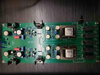
Board is a 2016. Please see pic.
I am using a 2 secondary (18v each) transformer, wired in series. I read about AC 36V from AC1 - AC2 and about DC 47V after the diodes.
Not everything is wired up. I wanted to check power supply part first. The relay power is ~23.8V (Across D10, D11) . Is that correct ?
Neither V+ to ground (measures 0.7V) nor V- to ground (measures -1.7V) move when I turn pots R9/R10 (Tried limit to limit).
Am I missing a ground? What was the 24 hour wire ? I tried searching for that reply, but didn't find it. I thought better to ask first.
Attachments
check parts positioning once more
voltages at BD transistor pins?
my guess is that you swapped BD transistor positions
voltages at BD transistor pins?
my guess is that you swapped BD transistor positions
\
Thank you ZM. I had the IRFs swapped. At +/- 15v now. I will list the previous measurements, since I did it already.
Do you recommend checking anything else because of this error?
The best I can tell, parts positioning is correct. I checked all transistors again (I had first checked all the BD, BC. While I was writing this, I realized I had not checked IRF. That was the issue).
Whatever error I made seems symmetric - i.e. same on both halves
Voltages wrt ground on BD pins (measured left to right on board):
BD139
1.4, 23.3, 2
BD140
-3, -23.2, -2.4
Voltage drops (V)
R1 21.1
R3 0.6
R2 20
R6 0.6
check parts positioning once more
voltages at BD transistor pins?
my guess is that you swapped BD transistor positions
Thank you ZM. I had the IRFs swapped. At +/- 15v now. I will list the previous measurements, since I did it already.
Do you recommend checking anything else because of this error?
The best I can tell, parts positioning is correct. I checked all transistors again (I had first checked all the BD, BC. While I was writing this, I realized I had not checked IRF. That was the issue).
Whatever error I made seems symmetric - i.e. same on both halves
Voltages wrt ground on BD pins (measured left to right on board):
BD139
1.4, 23.3, 2
BD140
-3, -23.2, -2.4
Voltage drops (V)
R1 21.1
R3 0.6
R2 20
R6 0.6
Last edited:
Board is a 2016. Please see pic.
I am using a 2 secondary (18v each) transformer, wired in series. I read about AC 36V from AC1 - AC2 and about DC 47V after the diodes.
Not everything is wired up. I wanted to check power supply part first. The relay power is ~23.8V (Across D10, D11) . Is that correct ?
Neither V+ to ground (measures 0.7V) nor V- to ground (measures -1.7V) move when I turn pots R9/R10 (Tried limit to limit).
Am I missing a ground? What was the 24 hour wire ? I tried searching for that reply, but didn't find it. I thought better to ask first.
Oh boy, the "24 hour wire" was Zenmods poking fun at me taking over 24 hours to add a wire to ground my Iron pre. It was not in a case and hummed badly. He suggested adding a temporary wire from ground of Iron pre to ground of power amp until Iron pre was in a chassis with something to ground to.
After whineing for 24 hrs I added the wire. Sorry if I caused you any grief about 24 hrs wire.
Russellc
Now look, you've gone and messed up two of us! If anyone wants to see unimportant 24 hour wire, I posted a pic a while back. Nothing to see, just a temp ground until chassis arrived.
Russellc
Russellc
\
Thank you ZM. I had the IRFs swapped. At +/- 15v now. I will list the previous measurements, since I did it already.
Do you recommend checking anything else because of this error?
The best I can tell, parts positioning is correct. I checked all transistors again (I had first checked all the BD, BC. While I was writing this, I realized I had not checked IRF. That was the issue).
Whatever error I made seems symmetric - i.e. same on both halves
Voltages wrt ground on BD pins (measured left to right on board):
BD139
1.4, 23.3, 2
BD140
-3, -23.2, -2.4
Voltage drops (V)
R1 21.1
R3 0.6
R2 20
R6 0.6
Looks like you are there, time to put tunes to it. If no chassis yet, get a pizza board, piece of wire with alligators (24 hour wire).
I also have 2016 boards, BTW. No jumpers for 12 dB, but Zenmods told how to slice and dice to get one few posts back. I'm finding 6 to be enough mostly.
Russellc
- Home
- Amplifiers
- Pass Labs
- What's wrong with the kiss, boy?