I
if you take 600CT:600CT , that's practically 4 windings of 150R (nominally) ......
you can use that one as 1:1+1+1 , resulting in 1+3 , having gain of 4V/V , which is 12db
If connected as 1:1+1+1, I get 3V/V and 9dB, and connected as 1+1+1+1, I get 4V/V and 12dB...right?
some additional info , just to have slightest idea about exact xformers?
though , if fingernail size , no good
though , if fingernail size , no good
By far the most common on google search.
Specification:
Model: EI14
AC impedance : EI14 600 : 600 Ohm
Item : Audio transformer
Inductance : 290mH (±20%)
DC resistance : 135(±%)
Windability : Double-wire winding
Quality &wire diameter : QA-1 0.06MM
Primary coils : 800 turns
Secondary coils : 800 turns
Alternating-current impedance value : 600
Size: 2.2cmX1.4cmX1.3cm(LXWXH)
Material: Nickel alloy
Color: Red
it's written , see on on bottom one
regarding CMOQ-4 , see attached
if you did as drawn , without getting close to 1Vin/4Vout , something is fishy with your measurements ......
Hi Zen Mod,
Can the Cinemag’s be used and work with the B1 ver1, or is this only a ver2 stable upgrade? I’ve read that the two designs are slightly different.
Thank you
yes , it can
just omit that series resistor on output of buffer
you need all the 00 of buffer
Thanks for your reply Zen Mod. Just looking at the schematic on PassDiy, would that be the 221k resistor at R105/205 coming off of Q101/201?
Thank you
Attachments

Thanks for your reply Zen Mod. Just looking at the schematic on PassDiy, would that be the 221k resistor at R105/205 coming off of Q101/201?
Thank you
Output reference...
nope
put shortie instead of R104,R204
or nice looking 0R resistors

Thanks for clarifying Zen Mod! R104/204 was actually my first choice but I second guessed myself. Still learning how to interpret and follow the wiring diagrams and component connections. I’ll read through Nelson’s circuit description again. One day I’ll get to all of Papa’s papers to get a better understanding of his circuits 😊
Does the same apply when adding iron to versions of the Salas DCB1 regarding pulling the series resistor on the output?
I have a black Hypnotize version which to my understanding was just an aesthetic pcb color choice by Tea Bag when he had these boards made. The circuit and layout shown appear to be identical to my board.
I’ve circled what I think is the series output resistors that would have to be removed in each image...which of course are some of the fancy Texas Componets foils I splurged on.
I’d just like confirmation I’ve got things right before I might try this.
Attachments

Thanks Zen...thought of another question 🙄
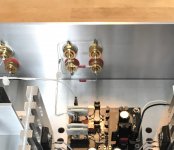
I have my DCB1 wired with two pair of output RCAs so that I can send the signal to a powered sub and my ACAs driving full range drivers in horns currently.
There is a 100 Ohm resistor in series with the positive signal wiring between the first and second pair of outputs. It was advised to add the resistor between the outputs in the DCB1 build thread. I think this was related to maintaining proper buffer operation?
I want to keep the dual outputs.
I have a B5 I would like to implement in my next stage of this system’s evolution.
The sub may still be desired.
One set of outputs would go to the sub and the other would connect to the B5. The B5 in turn would be driving separate amplifiers for the high and low frequencies.
Is there anything I need to worry about as far driving the additional equipment or how I am initially dividing the signal in the DCB1 when installing the iron just before the dual output RCAs?
I will be going into the DCB1 to try some different pots and rework the signal wiring with some shielded cable as well as trying to improve the grounding layout. So now is the time to sort it all out.
Pic below of the outputs for reference.
Thanks again in advance.
Attachments
at output side of gadget you can keep those 100R as sort of separating parts between two outputs
even if I would use lower value - 22 or 33R , or not at all
in my Iron Pumpkins I'm using just wires between paralleled outputs , no biggie
even if I would use lower value - 22 or 33R , or not at all
in my Iron Pumpkins I'm using just wires between paralleled outputs , no biggie
I'd appreciate a list of transformer options for iron pre, european ones more so.
Also, what would be the tech specs for a custom made standard EI. Such as core size, wire size, number of turns or impedance / dc resistance.
There,s a guy here who can make them. Being a guitar freak too I could even vacuum wax pot them though that what probaly be unnecessary.
Also, what would be the tech specs for a custom made standard EI. Such as core size, wire size, number of turns or impedance / dc resistance.
There,s a guy here who can make them. Being a guitar freak too I could even vacuum wax pot them though that what probaly be unnecessary.
Also there seems to be a number of 1200:1200 transformers on offer. Some center tapped on primary and secondary coil. Could those be used? Those could give +6db with galvanic isolation too?
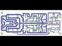
Mr. Zen, iskra tl-1m 600:600 comming in... for 1:2 connect all colis in series, connect everything to amp in both ends and tap the buffer + in the middle?
yup
excellent xformers
take care of windings phase ... observe red dots on edited pic
edit:
1 to GND
2+3 short
4+5 short , that's IN (from buffer)
6+7 short
8 OUT
that way you'll have 6db gain
excellent xformers
take care of windings phase ... observe red dots on edited pic
edit:
1 to GND
2+3 short
4+5 short , that's IN (from buffer)
6+7 short
8 OUT
that way you'll have 6db gain
Attachments


Last edited:
- Home
- Amplifiers
- Pass Labs
- What's wrong with the kiss, boy?