Hi, today i add other microcap simulator results.
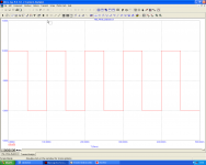
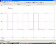
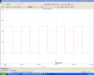
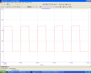
Square wave at 10, 1k, 10k, 100kHz.
Square wave at 10, 1k, 10k, 100kHz.
Attachments
The RED Version
Now I would like to present an enhanced version of this circuit.
I have called it "RED" because of the better performance as the Ferrari that has a more powerful engine and especially a high power consumption. 😡
Maybe I overdid it, maybe it's more fair to compare it to a Fiat 500 Turbo.
This scheme as the previous one does not use GNFB and its performance are true performance. The scheme is very simple but the selection of the components must be very strict.
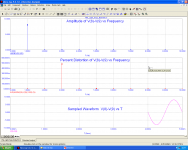
Please find attached some images taken with the simulator.
Others will follow after.
Francesco Corrado
Now I would like to present an enhanced version of this circuit.
I have called it "RED" because of the better performance as the Ferrari that has a more powerful engine and especially a high power consumption. 😡
Maybe I overdid it, maybe it's more fair to compare it to a Fiat 500 Turbo.
This scheme as the previous one does not use GNFB and its performance are true performance. The scheme is very simple but the selection of the components must be very strict.
Please find attached some images taken with the simulator.
Others will follow after.
Francesco Corrado
Attachments
I am attaching more images relating to measures of distortion of the Red version to:
 Notes: Because I realized that in the model of Vfet, the author did not consider the parasitic capacitances of the component, please You do not consider all the previous posted measures relating to AC and Square Wave analysis. I'm sorry.
For the 2SJ28 I expect compared to a 2SJ50 as an input capacitance slightly smaller than that or approximately equal and an output capacitance equal or slightly greater to that.
Have any of you has a better idea?
- 1 W
- 10 W
- 25 W
Notes: Because I realized that in the model of Vfet, the author did not consider the parasitic capacitances of the component, please You do not consider all the previous posted measures relating to AC and Square Wave analysis. I'm sorry.For the 2SJ28 I expect compared to a 2SJ50 as an input capacitance slightly smaller than that or approximately equal and an output capacitance equal or slightly greater to that.
Have any of you has a better idea?
Attachments
cool, i discovered that the 2sk79 i once took from a radio who was to be discarded, is a v-fet :O . as i recall there was a single one, in the tuner area. i noticed the k79 and knew it was at least a nice fast small signal fet. i plan to apply it.
The author did not consider the parasitic capacitances of the component
Oh, I most certainly considered them; they're just not included in the model you're using. The model included in the current issue of Linear Audio Volume 6 includes static interelectrode capacitances, so when choosing them you must consider the operating point. I recommend the new model over the Koren model you got from my blog, but if you want to cobble some static capacitances into the old model it wouldn't be difficult. If you want dynamic capacitances you'd have to figure out what they are first, since we don't have a datasheet.
Oh, I most certainly considered them; they're just not included in the model you're using. The model included in the current issue of Linear Audio Volume 6 includes static interelectrode capacitances, so when choosing them you must consider the operating point. I recommend the new model over the Koren model you got from my blog, but if you want to cobble some static capacitances into the old model it wouldn't be difficult. If you want dynamic capacitances you'd have to figure out what they are first, since we don't have a datasheet.
Thanks Mike for the news.
I have bought the article. I hope there is a model for 2SJ28 also.
-----------------------------------------------------------------------------
Since I will present a simulation with CCS load I need a model for IXYS IXTH16N10D2
Thanks, Francesco
I'm waiting for the progress of your sim MOS57, before i Do my project so as not to waste my rare Vfets...
So we need a balanced input?...maybe a concertina phase splitter and a triode pre will do the job or Jfets as well.
So we need a balanced input?...maybe a concertina phase splitter and a triode pre will do the job or Jfets as well.
I'm waiting for the progress of your sim MOS57, before i Do my project so as not to waste my rare Vfets...
So we need a balanced input?...maybe a concertina phase splitter and a triode pre will do the job or Jfets as well.
Yes you need balanced output.
These amps are high sensibility, so concertina tube is very good. (no voltage gain is need)
Alternatively you can use simple signal transformer unbalanced input to balanced output.
I recommend Jensen and Cinemag as news or Triad and UTC as vintage.
Transformers and cables must be shielded. 😎
Last edited:
you use 2 j28 sits... can I use 3 or 4 J18 parallel without any resistor value adjustments?
I also have k389 bl but only 2, can I use K117 BL or k246 GR which i have lots of them?
I also have k389 bl but only 2, can I use K117 BL or k246 GR which i have lots of them?
you use 2 j28 sits... can I use 3 or 4 J18 parallel without any resistor value adjustments?
I also have k389 bl but only 2, can I use K117 BL or k246 GR which i have lots of them?
Hi, you must select Vfets for Vgso. If they have near value ok, you can parallel it together without added resistors, if no you must insert little resistors (0,22-0,47 Ohm) from each source to the relative output terminal. These resistors lower the max output swing so the max power.
For the White version the Vfet power dissipation is almost 45 W each. It is a value that is possible for your Vfet yet, but need a very large heatsink to maintain temp very low
In the next i will show a version with CCS in which the Vfet dissipate only 36 Watt each for a more easily use of your 2SJ18.
Second question:
you can parallel 2 x 2SK117BL (selected for min 5-6mA Idss each) to substitute the 2SK170V. 😉
Last edited:
Hi, you must select Vfets for Vgso. If they have near value ok, you can parallel it together without added resistors, if no you must insert little resistors (0,22-0,47 Ohm) from each source to the relative output terminal. These resistors lower the max output swing so the max power.
For the White version the Vfet power dissipation is almost 45 W each. It is a value that is possible for your Vfet yet, but need a very large heatsink to maintain temp very low
In the next i will show a version with CCS in which the Vfet dissipate only 36 Watt each for a more easily use of your 2SJ18.
Second question:
you can parallel 2 x 2SK117BL (selected for min 5-6mA Idss each) to substitute the 2SK170V. 😉
Okay noted...I do have a customized heatsinks intended for class A amps made from Mac Processors HS and Aluminum angle bars plus an optional fan if needed.
I will wait for your CCS version and also want to try the choke loaded from Juma to see.
The Light Version
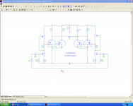
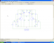
As promised, today I show the final circuit of a number of iterations, which, in my opinion, is the best compromise between conflicting requirements: low power dissipated by Vfet, higher power output, lower distortion.
The input circuit is an high current SRPP (approximately 28 mA) that makes use of 2N4392 type JFET. For the function of CCS I used the famous Hitachi 2SJ162.
Compared to the first version (the White) improvements have been tangible:
Final Note: not necessarily the sound of this latter circuit will be better than first.
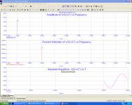
THD analisys is for 12 - 10 - 4 - 1 Watt
As promised, today I show the final circuit of a number of iterations, which, in my opinion, is the best compromise between conflicting requirements: low power dissipated by Vfet, higher power output, lower distortion.
The input circuit is an high current SRPP (approximately 28 mA) that makes use of 2N4392 type JFET. For the function of CCS I used the famous Hitachi 2SJ162.
Compared to the first version (the White) improvements have been tangible:
- 12 W vs. 10 W of output power
- 32 W vs 45 W of power dissipated for each Vfet
- Lower distortion at all measured power (you can compare the corresponding graphs).
Final Note: not necessarily the sound of this latter circuit will be better than first.
THD analisys is for 12 - 10 - 4 - 1 Watt
Attachments
-
 Light_Srpp BabySit.png42.8 KB · Views: 404
 -
 Light_Srpp BabySit_Distortion_Analisys_12W.png54.6 KB · Views: 392
 -
 Light_Srpp BabySit_Distortion_Analisys_10W.png53 KB · Views: 366
 -
 Light_Srpp BabySit_Distortion_Analisys_4W.png54.7 KB · Views: 363
 -
 Light_Srpp BabySit_Distortion_Analisys_1W.png57.9 KB · Views: 380
Last edited:
you use 2 j28 sits... can I use 3 or 4 J18 parallel
2SJ28 can in some cases be replaced vy 2x 2SJ18 in parallel, if the 2SJ18 are the same rank. It would be even better if they are further selected for similar Vgs at at a number of Vds and Id conditions (usually two Vds and two Id within ranges that normally appear in the intended circuit, will give you a good match).
It should also be noted that inserting small resistors in the sources will do nearly nothing to improve current sharing. Consider this: one rank number difference is about 2.5V Vgs difference at Id=100mA and Vds=50V. This means that if you wanted to parallel two VFETs of one rank difference, the source resistor would have to have a voltage drop of about 2.5V on the lower rank VFET, at 100mA, i.e. it would need to have a value of 25 ohms. Clearly this is completely useless. In class A it gets a bit better, but still about 2.5 ohms for 1A current. In other words, to get reasonable current sharing in one operating point, you get worse performance at lowest and highest currents.
Also, within one type of VFET variations can be huge. For instance, rank 2 2SK60/2SJ18 have half the mu and twice the Vgso of rank 7. On a curve tracer they look so different you would think they are a completely different part. In other words, allof these simulations can be hopelessly inaccurate unless it's well understood which exact VFET is in use. And lest one thinks I am pulling this data out of a hat, I have several hundred VFETs at hand and they have all been tested on a Tek curve tracer.
Regarding the amp project - in fact, if you can drive the increased input capacitances of a parallel pair of J18 instead of a J28, it's an easier job to dissipate heat from two VFETs than it is from one. Each J18 is rated 60W dissipation at the same conditions as a J28, that is rated 90W dissipation, so a pair of J18s has a 30W max dissipation advantage. This is quite welcome in a class A design.
Regarding the topology itself, it has the disadvantage that the output impedance is twice than of a single VFET. However, if a center tapped choke or even an autoformer was used instead of the two resistors or CCSs, the efficiency would double and the output impedance would halve. If you take steps for good symmetry, the choke or autoformer could be a low voltage winding on a toroid (or custom wound single winding toroid), or even better C-core transformer, which would make it very wideband. The low impedances in the circuit make it fairly easy to wind this, no special techniques required.
Thanks ...yes 13 of my J18's are of the same rank..
using a center tapped former is a very nice option since i do have a autotransformer (stepdown 220 to 110, 750Va) can I use this thing without making a gap?
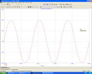
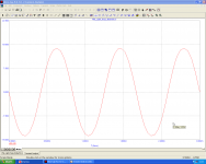
Sorry, I had forgotten the transient analisys,
The CCS use a latfet J162 and what is the value of the Zener diode you use...Can I use vertical mosfet such as irfp9240 as CCS and what Zener value?
Last edited:
The CCS use a latfet J162 and what is the value of the Zener diode you use...Can I use vertical mosfet such as irfp9240 as CCS and what Zener value?
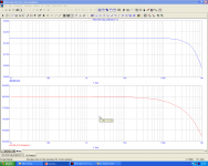
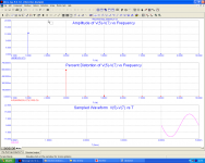
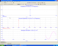
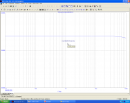
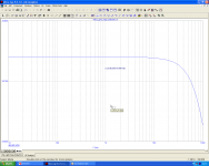
The 2SJ162 was not chosen at random. That 's what gave me the best results both in simulation against the harmonic distortion and in the extension of the bandwidth.
I enclose explanatory graphs, although as already mentioned the vfet with the current model are seen as components devoid of parasitic capacitances.
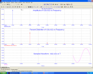
First graph referred to 2SJ162 CCS, the second to IRF9540 (no model for IRFP9240) but result must be similarly. I have tried other lateral and vertical mosfet: Hitachi is the best
I have zoomed up the scale to better highlight the differences.
The scale is the same for both graphs: 10-100KHz X-axis, Y-axis 0.2 dB ; Id current=2,11 A
Actually the zeners used for J162 are of 3,0 V type.
Best regards
Attachments
Last edited:
you use irf9540 more than 4v zener is needed,,,the j162 is lower vgs so you use 3v for 2.11A idle. Is this idle current 2.11a per Vfet or or for the 2?
What should be the minimal VA rating of my PSU for 2Channel (stereo).
What should be the minimal VA rating of my PSU for 2Channel (stereo).
JUNM,
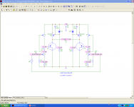
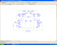
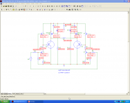
You are right, i not exposed these details yet because too much data on the same scheme would be confused.
Now I post the 3 designs related to voltages, currents, and power enveloped in the circuit, respectively. . (I hope you referring to the version with CCS).
So stereo version dissipate 300 Watt, therefore you need 400 or 500 VA transformer. I recommend double C (or EI if not possible) with separate windings for primary and secondary
ROTHACHER
Waiting to come the new model, I would like to ask:
Have you tried the old model in simulated circuits as Spice or Microcap? (parasitic capacitances apart)
Thanks in advance
Attachments
Last edited:
- Status
- Not open for further replies.
- Home
- Amplifiers
- Solid State
- What to do with this Sony V-FETS?