Are these GE diodes need to be in the heatsink with the VFET's to sense variation in temperature?
Are these GE diodes need to be in the heatsink with the VFET's to sense variation in temperature?
The simulator makes the Dynamic Dc analysis in relation to ambient temperature, which then it should be the temperature of each individual component. But we know that in practice this is not true.
In pratical case the actual temperature of each component depends on many factors. We briefly mention some of them:
- the general layout
- the size of the component and therefore its ability to dissipate the heat
- the size of the heat sinks and their position (horizontal, vertical, internal or external to the cabinet).
- the structural characteristics of component (a metallic resistance increases its value as the temperature increases, a carbon composite resistance decreases its value as the temperature increases.
These are all things that simulator not knows and thus can not calculate.
It was raised a problem and we have found solutions to stem it at the theoretical level, it being understood that in the conditions assumed in the model.
The reality is more complex as these additional variables, are difficult to verify in advance. The study has, however, provided a fairly simple method to minimize the problem.
It should once again reiterate that the circuit, also as it was originally presented, was safe, as a result of the choice made, it limits the current and therefore the power dissipation as the temperature increases.
Also, operating it in class A, there is not even the problem of increased crossover distortion.
The only slight drawback might be a slight loss of power. At the rated current of about 2.10 A what you think may affect in decreased power a decreased current of 10 or even 100 mA?...
However it is better a bit undercompensate than overcompensate
Last edited:
do you have any link to where i can order Jfets such as 2n4392...i found 2n4393 in RS but very expensive. In fact they are more expensive that the Cost of 2SJ18 that I bought. How about using depletion mosfet such as 10m45 or LND2540 or any other?
do you have any link to where i can order Jfets such as 2n4392...i found 2n4393 in RS but very expensive. In fact they are more expensive that the Cost of 2SJ18 that I bought. How about using depletion mosfet such as 10m45 or LND2540 or any other?
10m45 is a current regulator not mosfet.
LND2540 have much high input capacitance.
In general mosfet have higher noise and distortion than jfet, also.
For 2N4392 try these 2 sellers on Ebay:
2N4392 Transistor N-FET 40V IDSS 25mA TO18 | eBay
[2 pcs] 2N4392 oryg. Vishay-Siliconix N-Channel J-FET TO18 | eBay
The BLACK version
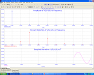
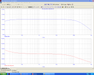
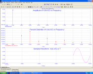
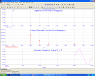
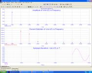
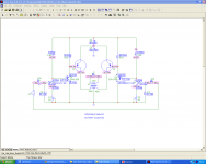
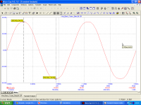
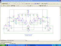
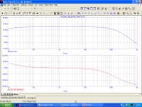
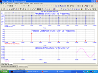
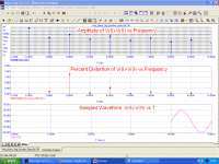
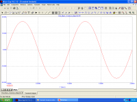
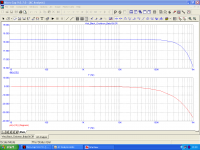
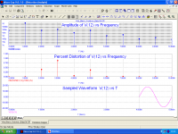
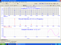
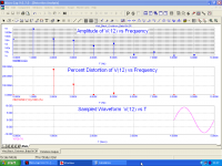
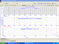
To meet the demand of people asking for a version with the output transformer, I have designed two different power amplifiers, the smallest of which is shown below, along with the graph of the frequency analysis and distortion at 1-10-20 Watt / 8 Ohms
To meet the demand of people asking for a version with the output transformer, I have designed two different power amplifiers, the smallest of which is shown below, along with the graph of the frequency analysis and distortion at 1-10-20 Watt / 8 Ohms
Attachments
-
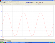 Little_Black_BabySit_Transient_Analisys.png43.8 KB · Views: 315
 -
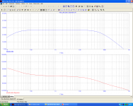 Little_Black_BabySit_AC_Analisys.png47.6 KB · Views: 303
 -
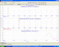 Little_Black_BabySit_Distortion_Analisys_1W.png55.8 KB · Views: 308
 -
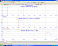 Little_Black_BabySit_Distortion_Analisys_10W.png55.8 KB · Views: 298
 -
 Little_Black_BabySit_Distortion_Analisys_20W.png56.7 KB · Views: 308
 -
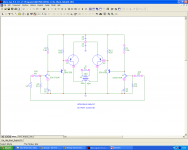 Little_Black_BabySit.png45.8 KB · Views: 144
Last edited:
Thanks Mos57... i think this transformer coupled one is more appropriate for me...you use K373, a 100v jfet in the input, does it necessary to have this Hv jfet or any jfet will do. The OPT is labeled 45m+45m// 25m...is this in meter, millihenry's or what?
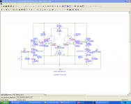
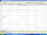
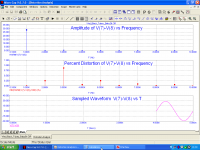
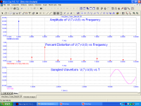
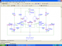
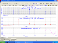
This is the high power version with output transformer. Also if I have declared as a 90 Watt amp, it can also delivers 100 Watt on 8 Ohm load without clipping.
Images attached for circuit, transient, AC and distortion analisys for 90,50,1 Watt/8 Ohm.
Best regards, Francesco.
Images attached for circuit, transient, AC and distortion analisys for 90,50,1 Watt/8 Ohm.
Best regards, Francesco.
Attachments
-
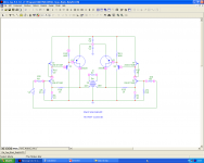 Srpp_Black_BabySit.png46.1 KB · Views: 152
 -
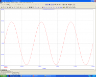 Srpp_Black_BabySit_Transient_Analisys.png44.1 KB · Views: 122
 -
 Srpp_Black_BabySit_AC_Analisys.png45.4 KB · Views: 82
 -
 Srpp_Black_BabySit_Distortion_Analisys_90W.png54.3 KB · Views: 72
 -
 Srpp_Black_BabySit_Distortion_Analisys_50W.png56.4 KB · Views: 73
 -
 Srpp_Black_BabySit_Distortion_Analisys_1W.png56.1 KB · Views: 87
Thanks Mos57... i think this transformer coupled one is more appropriate for me...you use K373, a 100v jfet in the input, does it necessary to have this Hv jfet or any jfet will do. The OPT is labeled 45m+45m// 25m...is this in meter, millihenry's or what?
In this circuit is necessary high voltage Jfet. You must substitute it with another high voltage jfet and about same Idss and gm. 45+45 means 45 mH+45 mH inductances on 2 primaries and 25 mH on secondary.
I didn't notice that you use two supplies, now i really know we have to use hv Jfets. I have K223 but only 80V and almost same rating as K373. At 96v, I presume that voltages across each jfet will be half(48v) or lesser since its srpp, am I right?
Can you give us the OPT details...core size, wire size etc.and the schematics with current and voltages on each node. What should be the driver tranny?
Can you give us the OPT details...core size, wire size etc.and the schematics with current and voltages on each node. What should be the driver tranny?
I didn't notice that you use two supplies, now i really know we have to use hv Jfets. I have K223 but only 80V and almost same rating as K373. At 96v, I presume that voltages across each jfet will be half(48v) or lesser since its srpp, am I right?
Can you give us the OPT details...core size, wire size etc.and the schematics with current and voltages on each node. What should be the driver tranny?
I enclose schematics of the small and bigger amplifiers with out transformers with specified voltage values of the nodes and circulating currents.
You are right for JFETs in SRPP circuit, not for other scheme.
Driver transistors are 2SA1358, or 2SB649A or 2SA1011.
For construction details of the output transformers please contact your supplier. It is sufficient that you tell the value of the inductance and the effective power.
Last edited:
Because the transformer has it's centerpoint grounded, the trafo could (and probably should) be made as an autoformer, which would make it signifficantly easyer to make.
Because the transformer has it's centerpoint grounded, the trafo could (and probably should) be made as an autoformer, which would make it signifficantly easyer to make.
An autoformer with seconday as the output terminal?
Most autoformers i know does not have secondary only single winding for step up or step down types.
How about using a autoformer as Choke and connect directly the speaker between the drains, one setback of this is when one of the Vfet dead the speaker will get affected or burned.
@mos57...thanks for the values..
The Hybrid version
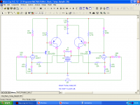
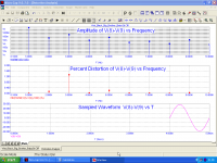
Given the relative difficulty in finding high-voltage jfet I made a virtue from necessity, and so, also for the lovers of the tubes, I propose a hybrid version that uses high mu triodes in the input section.
It would be desirable also to use high-gain nuvistor as type 6DS4 or 8058 but I do not have the models.
Please note that this circuit uses the better devices (IMHO) in their respective categories:
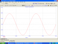
I enclose circuit and related measures. Distortion analisys are for 50, 25, 1 Watt / 8 Ohm
Francesco
Given the relative difficulty in finding high-voltage jfet I made a virtue from necessity, and so, also for the lovers of the tubes, I propose a hybrid version that uses high mu triodes in the input section.
It would be desirable also to use high-gain nuvistor as type 6DS4 or 8058 but I do not have the models.
Please note that this circuit uses the better devices (IMHO) in their respective categories:
- Tubes for voltage amplification
- Transistors for current amplification
- Vfet for power amplification.
I enclose circuit and related measures. Distortion analisys are for 50, 25, 1 Watt / 8 Ohm
Francesco
Attachments
-
 Black_Tubey_BabySit.png43.5 KB · Views: 341
 -
 Black_Tubey_BabySit_Transient_Analisys.png40.8 KB · Views: 321
 -
 Black_Tubey_BabySit_AC_Analisys.png41.5 KB · Views: 289
 -
 Black_Tubey_BabySit_Distortion_Analisys_50W.png52.2 KB · Views: 92
 -
 Black_Tubey_BabySit_Distortion_Analisys_25W.png50.8 KB · Views: 87
 -
 Black_Tubey_BabySit_Distortion_Analisys_1W.png50.5 KB · Views: 92
Last edited:
wow a hybrid...well i think this my other alternative since i do have hi mu tubes like 12ax7. I think this will be the one i can start off since i have the tubes...I just want to try a PA Output trafo for the output....I have an 50w opt from a PA system with 4-8-16-70-100v secondary....i will just use the 8 ohm taps.
Thanks mos57 ..i also want to give it a Tube concertina or cathodyne phase splitter to address the balanced input...
BTW, what is the idle current on each Vfets. Can you show the node voltages?
Thanks mos57 ..i also want to give it a Tube concertina or cathodyne phase splitter to address the balanced input...
BTW, what is the idle current on each Vfets. Can you show the node voltages?
The B4 - Black Big Brother BabySit
Today i show a booster version of tube BabySit.
It can deliver up to 220 W on 8 Ohm speaker.
Much more power should be delivered with 4 Ohm speaker, but i not show here because i not like very high power amplifiers for home.
Notes: For which is interested in 4 Ohm version please add another 2 pair of Vfets (for a total of 5 pairs)
In following the images for circuit Schematic, Transient analisys, AC analisys, and Distortion analisys for 220, 150, 100, 50, 1 Watt on 8 Ohm load.
Attachments
-
 Black_Big_Brother_BabySit.png46.9 KB · Views: 160
 -
 Black_Big_Brother_BabySit_Transient_Analisys.png40.2 KB · Views: 159
 -
 Black_Big_Brother_BabySit_AC_Analisys.png42.8 KB · Views: 80
 -
 Black_Big_Brother_BabySit_Distortion_Analisys_220W.png53.7 KB · Views: 75
 -
 Black_Big_Brother_BabySit_Distortion_Analisys_150W.png51 KB · Views: 75
 -
 Black_Big_Brother_BabySit_Distortion_Analisys_100W.png51.3 KB · Views: 75
 -
 Black_Big_Brother_BabySit_Distortion_Analisys_50W.png50.3 KB · Views: 73
 -
 Black_Big_Brother_BabySit_Distortion_Analisys_1W.png50.5 KB · Views: 80
woow...lot of power...and J28...
I think i will just settle for the parallel J18 a total of 4 per channel...50w ab is enough and I think heatsinks will be smaller than of those in CCS and Class A schema's.
I think i will just settle for the parallel J18 a total of 4 per channel...50w ab is enough and I think heatsinks will be smaller than of those in CCS and Class A schema's.
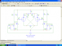
The Circlotron variation
One other alternative to use Vfet of the same polarity is the circlotron known to you all. I designed a circuit like this but this has some variations.
Firstly this circlotron is not used in the classic follower topology but it has voltage gain.
In addition, the output signal is at ground level for the continuous components.
Note also the reduced quantity of power supplies respect to similar circuits
This is' the first time I show this configuration in practice, although the schematic was studied at the time of my patent: see also this link: http://www.diyaudio.com/forums/pass-labs/153912-circlotron-meditations.html
I enclose scheme, transient analisys, AC analisys, and Distortion analisys for 20,10,5, 1 Watt / 8 Ohm.
Attachments
-
 Black_Circlotron_BabySit.png42.5 KB · Views: 147
 -
 Black_Circlotron_BabySit_Transient_Analisys.png39 KB · Views: 148
 -
 Black_Circlotron_BabySit_AC_Analisys.png38.9 KB · Views: 87
 -
 Black_Circlotron_BabySit_Distortion_Analisys_20 W.png49.2 KB · Views: 86
 -
 Black_Circlotron_BabySit_Distortion_Analisys_10 W.png49.4 KB · Views: 74
 -
 Black_Circlotron_BabySit_Distortion_Analisys_5 W.png48.5 KB · Views: 71
 -
 Black_Circlotron_BabySit_Distortion_Analisys_1 W.png50 KB · Views: 75
- Status
- Not open for further replies.
- Home
- Amplifiers
- Solid State
- What to do with this Sony V-FETS?