I see beginnings of a YT channel on the subject. Maybe you get reimbursed for trying to program the different available models. Attract attention to your business, when viewers realize you've got it figured and your controller "just works" with anything!These are the joys of working with many different loco manufacturers who all interpret spec differently.
I refurbished the Westinghouse reversing device in a 1950-built Baldwin DRS-6-6-1500 diesel locomotive at the Arizona Railway Museum. The reverser has a large, segmented copper drum that rotates partially to reverse the polarity of the DC current applied to the traction motors, and hence the direction of the locomotive’s travel. This device does not switch under load, so the contact surfaces are worn but not pitted. I wish I could say the same about the power contactor that engages power once the reverser has moved.
The rotational force is applied by two air pistons, which in-turn are controlled by solenoid valves. In this case, the old leather piston cups were shot, so the reverser would not turn reliably. Hence, the locomotive sometimes moved in the wrong direction, clearly not a good thing!
Replacing the piston cups required a significant disassembly of the unit, including the drum. The drum was cleaned and polished, piston cylinders cleaned, and new neoprene piston cups installed.
This past weekend we fired up the 15,000 cu-in, 8-cylinder diesel prime mover and was gratified that the reverser now moves smoothly and reliably, and the locomotive moves in the correct direction every time! This has been an on-going problem for years, and required a big wrench in the cab to manually rotate the drum when it would not move correctly. Unit is about twenty-four inches overall height.
Sorry for the murky photo. The unit is inside the electrical cabinet, very close to floor level, making it very inconvenient to work on. The repair took about 4 weeks’ worth of Saturday mornings. Frequent breaks were needed for my sixty-five-year-old back and knees. And only one banged knuckle!

Traction motors operate at 600 VDC, current can be up to 2000A short-term. In operation at the museum, we rarely see more than 500A on the ammeter, and then only briefly. I never did like sticking my metal wrench in there to turn it manually.
Picture borrowed from web.
Have one of these. Changed electrolytic caps (many bad ones), cleaned, given a new volume pot and a good cleaning.
What a sound!
Can understand why some people like these machines!
I've been tinkering with the Mora clock (long case) I recently gave to my wife.

Having cleaned the next (using electrical switch cleaner on cotton bud on all the gear bearings and re-oiled using the proper oil), I got it running.
Getting the mechanism level and adjusting the beat was the key.
Simplest method is to mark the centre of the pendulum at rest on a bit of tape placed behind it.
Then push the pendulum to the right until a tick is heard, mark that spot.
Then push all the way to the left and mark the tock.
They should be equidistant.
Some fancier mechs have a clutch on the crutch so you can adjust. These oldies just have a bendable steel rod🙂
It's been bent a few times over it's long life!

It keeps remarkably good time for such a crude mechanism.
I don't have to reset the time very often at all!
Having cleaned the next (using electrical switch cleaner on cotton bud on all the gear bearings and re-oiled using the proper oil), I got it running.
Getting the mechanism level and adjusting the beat was the key.
Simplest method is to mark the centre of the pendulum at rest on a bit of tape placed behind it.
Then push the pendulum to the right until a tick is heard, mark that spot.
Then push all the way to the left and mark the tock.
They should be equidistant.
Some fancier mechs have a clutch on the crutch so you can adjust. These oldies just have a bendable steel rod🙂
It's been bent a few times over it's long life!
It keeps remarkably good time for such a crude mechanism.
I don't have to reset the time very often at all!
We used to get contact kits for contactors, so it was easier to refurbish them. Moving and fixed contacts in sets as per model and make.
Sometimes just the buttons can be found, rivet or braze as replacements for the burnt or pitted ones.
See if that works for you.
Another method is to clean off dirt from the contacts using a substitute for carbon tetrachloride, then spray something like CRC 2-26, which forms a protective film every time it breaks the contact, extends tip life.
The new designs do not allow that, have to throw them away.
Solid state relays have made contactors obsolete in many applications.
I repeat, no links with nakers of 2-26, here in India at least several companies use that as a description!
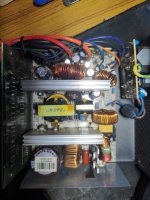
A 10" active Yamaha subwoofer for a friend >
The model claimed "Active Servo Feedback", but that was nothing more than monitoring voltage across a resistor.
The unit uses a Chip-Amp with nothing more than a flat metal panel for cooling > NO cooling fins at all.
The owner said no to adding a Heat Sink, so I added a 160 degree thermal switch for future protection.
( the Chip-Amp was dead due to overheating ... if it was mine, I would DEFINATELY add a Heat Sink )
You could have put a higher voltage rated chip amp, or replaced the plate amp inside, those are not so expensive here.
At least you got a new chip amp, which one was it?
At least you got a new chip amp, which one was it?
It is about 40V so a 1943/5200 plate amp would have worked better.
STKs are usually fake now, and the originals were known to fail suddenly.
They are quoted about $14 here, the plate amp without transformer is about half that, with heat sink.
Strange that Yamaha put a small heat sink on a unit that needs a hefty heat sink.
I have no links to Yamaha.
STKs are usually fake now, and the originals were known to fail suddenly.
They are quoted about $14 here, the plate amp without transformer is about half that, with heat sink.
Strange that Yamaha put a small heat sink on a unit that needs a hefty heat sink.
I have no links to Yamaha.
Last edited:
WOOPS > my brain somehow doubled a detail ...
The thermal switch I added was actually 80 degrees Celsius.
The thermal switch I added was actually 80 degrees Celsius.
YES >It is about 40V so a 1943/5200 plate amp would have worked better,
STKs are usually fake now, and the originals were known to fail suddenly.
They are quoted about $14 here, the plate amp without transformer is about half that, with heat sink.
Strange that Yamaha put a small heat sink on a unit that needs a hefty heat sink.
I have no links to Yamaha.
I still don't quite understand why Yamaha would choose such a device ???
Good, a current limiting circuit breaker is also a possibility, and a close to max rated fuse.
OnSemi took over Sanyo Semiconductor, and some STK modules were sold by OnSemi, seem to be no longer available.
But the choice of heat sink was Yamaha's selection.
I have seen similar speakers where the heat sink is exposed to ambient air, and sometimes a port allows air circulation inside the cabinet as well.
Maybe it was intended or designed for a lower ambient temperature, and found its way to a warm climate...
I have seen old Panasonic compressor catalogs, 15-25-35-40-45-52-60 Celsius ambient temperature models, and 110V / 60Hz, 220V / 50 Hz, 110V / 400Hz (aircraft duty) choices in single phase supply, for each BTU rating available (those are pretty standard series).
Panasonic at one time was the largest maker of rerigeration and air conditioning compressors, even today it is a large player, and they have many competitors like Copeland, Mitsubishi, Hitachi and others.
I used to make parts for a company that made portable split airconditioners, one of the directors had the Panasonic catalog, showed it to me, it was as thick as a telephone book, almost 70 mm IIRC.
So it was by chance that I came to know about it, I have no links to any entities named above.
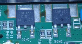
Haa, Forgot to update the fault. The issue were two faulty mosfets in parallel that was replaced.Looks like need to fix this lg tv asap. There was a some mini explosion noise and now status blink indicates power supply issue. WKP.
Attachments
i have one now on my banch. motordont stop spin but changes speed pressing either 33 or 45.Thorens TD105 with three faults
what were the 3x faults u have and what was the fix (without copywright 🙂
- Home
- Member Areas
- The Lounge
- What did you last repair?