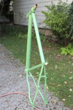
My every day bike.
It was completely broken:
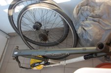
cracked rear rim (worn off from breaking)
worn out chain and gears, only one or two gears usable at all with dangerously jumping chain
flat tire (because of cracked rim)
rusty bowden housings and cables
completely worn off tire profiles
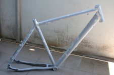
ugly scratched and dirty frame stickers and colours
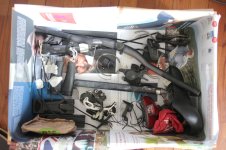
so I did a complete dismantling and renovation including frame painting and change to a rear disc brake (front will follow, but I wanted to reuse the hub dynamo).
the final test was a successful 796 km journey along the danube river!
It was completely broken:
cracked rear rim (worn off from breaking)
worn out chain and gears, only one or two gears usable at all with dangerously jumping chain
flat tire (because of cracked rim)
rusty bowden housings and cables
completely worn off tire profiles
ugly scratched and dirty frame stickers and colours
so I did a complete dismantling and renovation including frame painting and change to a rear disc brake (front will follow, but I wanted to reuse the hub dynamo).
the final test was a successful 796 km journey along the danube river!
Attachments


My latest is this odd Soviet era electrostatic voltmeter. What makes in interesting is as follows-
1) Electrostatic- no current on DC loading on AC is less than 50 pF.
2) AC RMS and DC
3) 70V full scale and measures as little as 10V
4) 10 MHz bandwidth- works to almost 30 MHz.
5) Uses optical to magnify the movement of the miror to a scale that has essentially no parallax. Similar to https://en.wikipedia.org/wiki/Mirror_galvanometer
This was made in 1968 it seems. It used a 6V flashlight bulb as the light source and even has a trasformer to power from line voltage.
I found an LED spotlight bilb that fit and with a little fiddling I got the optics working
Then It turns out the sensitivity has changed in the intervening 55 years. So sine the mechanism is so delicate I chose to recreate the scale. I took a photo and printed it rescaled to approx accuracy.
Finally getting it to zero correctly was the most challenging. I had to dismantle it enough to get to the lower zero adjust.
The light beam starts at the top, bounced off a mirror on the bottom, is reflected by more optics to the mirror on the movement, then goes to a mirror just below the meter scale, back to a mirror below the movement and then to the meter scale. In the light source is a wire that become the reference line on the display. I figure the whole light path is around 24 inches. Thats part of how it gets its sensitivity.
The company made a 30V version of this. There are a number of these being sold out of Ukraine (Where I got this).
I took a bunch of pictures whaile it was open.
There is a way to lube camera galvanometers, the pivot screw is loosened, and the pivot cleaned, then a tiny quantity of clock oil is applied with the tip of a sewing needle.
After that, the screw is adjusted for proper height with respect to the mechanism, no play, neither loose nor tight.
We have some people here who think Soviet technology was behind the curve in comparison to the West, this is yet another example that they were really on a more advanced level in comparison.
Only loosen pivot, if it comes out, kaput.
There may be videos about it on net.
Use a cleaning fluid to flush out old lube, dry, lube, set again.
About 1 to 2 mm is enough...more will cause the pivot to come out of its matching part.
There may be videos about it on net.
Use a cleaning fluid to flush out old lube, dry, lube, set again.
About 1 to 2 mm is enough...more will cause the pivot to come out of its matching part.
Its a taught band movement with a very thin wire maybe 40 or 50 awg. I did manage to get the zero adjusted. I confirmed the leakage is very low when the 10 Meg resistor is disconnected. 20v can take a minute or two to dissipate.
Its a great demo of finding a solution when you have different resources to work with.
Its case is pretty rough with a hole punched in it.
Its a great demo of finding a solution when you have different resources to work with.
Its case is pretty rough with a hole punched in it.
I repaired my Tivoli Model One. It wouldn't power up from mains. Transformer's primary was reading open. Due to few years ago the neutral wire was broken at a local substation by copper thieves, the line voltage rose to dual phase potential thus many devices went kaboom in my house and in the neighborhood. Couldn't readily find an exact same frame size Tx at the time and as it was still working on external DC I left it aside.
Revisited it the other day because someone with a pro machine said it was possible to rewind. Opened it to dig in but surprisingly no burned coil. It had a broken thermal fuse inside the primary. Tiny transformers usually don't. Bypassed it. Soldered a 100mA fuse on one leg of the AC inlet, covered it with heat shrink. Also replaced the tired enough smoothing cap with a fresh 4700uF 35V Nichicon FW. Its tricky to service or modify there because its a sandwich affair of no space to maneuver or put bit larger parts. I installed the fatter & taller cap behind the amp PCB upright with hot glue. Just a tiny clearing space was left between it and a wooden block used for screwing the back panel.
It works fine on mains again. Radio voices as intelligible as ever from the three inch Foster full ranger in the solid wood cabinet. It also utilizes a bottom reflex tube.
So if something bad happens with the AC powering of a Model 1 remember there's no mains fuse but there's a thermal fuse inside its transformer. At least this type.
Glad I wasnt nearby when they disconnected that conductor. Anyone get a Darwin award?Due to few years ago the neutral wire was broken at a local substation by copper thieves, the line voltage rose to dual phase potential
The service centre I worked at was part of the regional electricity board and we were always getting items for repair where contractors had cut though the neutral. Often several houses together were affected and all the TV's VCR's clock radios etc etc would come in. Far from a rare occurrence unfortunately. Many was the time though when unscrupulous customers would try their luck claiming that something had been damaged when it was obvious it was a derelict from a garage or loft. Mangled mechs in VCR's, that kind of thing.
Happy days 🙂
Happy days 🙂
No, didn't hear about an injured copper thieve then. We didn't receive any compensation from the electric power company either although we applied.Glad I wasnt nearby when they disconnected that conductor. Anyone get a Darwin award?
Had to buy a new fridge and several wall warts, fortunately could repair couple of gear on my own like the DVD player etc. Neighbors got air-cons hit.
It's a shame it couldn't have been put to a better use. Sometimes I think you believe otherwise?We have some people here who think Soviet technology was behind the curve in comparison to the West, this is yet another example that they were really on a more advanced level in comparison.
Hi,
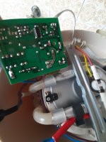
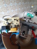
Do you think my Moulinex can be fixed.
Ligth at switch on but no heating anymore.
The diode in rhe middle measure 370 R in the two direction while the other seems ok with 750R in one direction.
The relay seems only to switch off the heater résistance after à while.
Any idea where to beginn please ?
Do you think my Moulinex can be fixed.
Ligth at switch on but no heating anymore.
The diode in rhe middle measure 370 R in the two direction while the other seems ok with 750R in one direction.
The relay seems only to switch off the heater résistance after à while.
Any idea where to beginn please ?
Attachments
Replaced second motor within a year on my parents Husqvarna Automower. So that's now close to 1000 EUR in parts alone in 6 years of use. For sure this looks like a great business model.
Only until the reviews catch up and sales tumble. But hey... Shareholders were happy for a little while.For sure this looks like a great business model.
Tom
More often than not the supply capacitor (yellow block) has lost capacity over time thus the aux supply does not work properly.Hi,
Do you think my Moulinex can be fixed.
Ligth at switch on but no heating anymore.
The diode in rhe middle measure 370 R in the two direction while the other seems ok with 750R in one direction.
The relay seems only to switch off the heater résistance after à while.
Any idea where to beginn please ?
Replace with a a self-healing safety X2-capacitor
^+1 to that. Similar thing happened to me a year or more back with a cooker:
https://www.diyaudio.com/community/threads/what-did-you-last-repair.313739/post-7409378
You must use a cap of the type @bucks bunny mentioned for safety. Don't even think of using any old cap here.
https://www.diyaudio.com/community/threads/what-did-you-last-repair.313739/post-7409378
You must use a cap of the type @bucks bunny mentioned for safety. Don't even think of using any old cap here.
It's been a long battle, but I think I finally fixed the garage door opener at our old house. Took some kicks at the cat to figure out what was wrong. Symptoms were that it basically ran unabated until it physically jammed and stalled the motor. What it turned out to be was a worn out main driveshaft bearing or race, which allowed sufficient play that a gear unmeshed from the matched gear driving the limit switch assembly. I found a failed unit for free and cannabalized the driveshaft assembly to swap in.
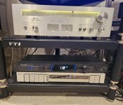
Well its not on the level of everyone else here but hey, I acquired an old 70's Akai tuner with blown lamps.
These are sealed in a wood box, not vented
No dust inside. Amazingly perfect inside and out; looks like it came off the assembly line yesterday.
Working perfectly. Cost me $70 and $12 for the 12v AC/DC LEDs.
Repair: replaced the blown lamps with LEDs.
Not quite matching my 80's Akai fancy programmable audio timer.
Attachments
Last edited:
My compressor.
This damn thing broke while I was applying the first coat of varnish on my new 4-way speakers. I was spraying the baffle when it dropped a valve – okay, not literally, since it doesn’t have valves, but whatever functions like a valve was obliterated, and the compressor lost all pressure.
Luckily, I had a spare kit with gaskets, the spacer and the valve-like parts to put everything back together and finish the first coat in time.
It has been in service for about 25 years already. I guess it’s time to retire it.
 .
.

This damn thing broke while I was applying the first coat of varnish on my new 4-way speakers. I was spraying the baffle when it dropped a valve – okay, not literally, since it doesn’t have valves, but whatever functions like a valve was obliterated, and the compressor lost all pressure.
Luckily, I had a spare kit with gaskets, the spacer and the valve-like parts to put everything back together and finish the first coat in time.
It has been in service for about 25 years already. I guess it’s time to retire it.
- Home
- Member Areas
- The Lounge
- What did you last repair?