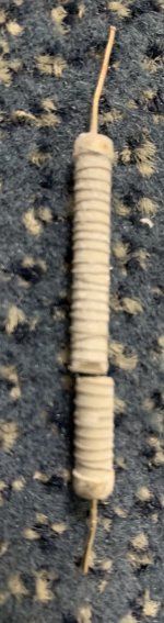
This is the inside of the Audio Grade 10 Watt resistor… I guess the ceramic tube was broken by my brute force to take the resistor apart, but the resistorwire was already broken.
Regards, Gerrit
Thanks.
It appears to be a cheaply wound hunk of crap.
I see windings crossed over windings, like someone wrapped it by hand, not machine wound.
china.
Hi Jean-Paul,
It wasn’t a cheap resistor at all, it was so called high-end “Audio Grade” quality. I bought it for another purpose, but it ended up in the position between chassis and audio ground.
To be honest, I’ve seen quite a few ceramic wirewound resistors blown over the years. Some turned browd or dark gray and were still OK, some drifted and some opened up.
The replacement resistor will be a better, ruggidized type.
Regards, Gerrit
What you pay for it is your fault 😉 It is cheap Chinese quality. Of course quality wire wound resistors can go defective and change color but that is when they dissipate. In this case nothing is dissipated, therefor the conclusion is that it is crap quality.
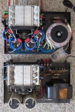
A pair badly abused Hafler 500s
A buddy bought a rough pair of bridged Hafler 500s, factory built, clean (untouched) internals... looks are deceiving...
BUT the moment you open the speaker fuse receptacle and find 4 different values, most slow blow and even one 30 amp slow blow. I was afraid to open it and even more reluctant to power it up into any speaker in my home (or garage, even) There was even a 30 amp slow-blow on a B+ line.
"A GUY" had been ABusing these otherwise "indestructible" amps in his garage, "banks of" 2 ohm configured/loaded 18" car stereo bass cabinets, he called "subwoofers" = can you imagine how wretched it must have sounded?
Meager current delivery to and reduced damping of massive drivers.
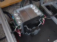
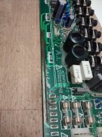
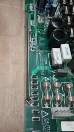
Both amps had blown output transistors (incidentally, these were my very first [BLOWN] Hafler amps, that I have touched or worked on) Before and after. The bottom is amp 2 before I "made it look like" the amp above. They are now completely rebuilt beasts with dual die Exicons. By any accounts ambitious / very worthwhile projects.
Amp 2 / image 2 (I now own) and have completely rebuilt the power module, as shown, it is now serving as a test amp to model and evaluate power supplies I am building. I am undecided on what P/S I want to use with it...
A buddy bought a rough pair of bridged Hafler 500s, factory built, clean (untouched) internals... looks are deceiving...
BUT the moment you open the speaker fuse receptacle and find 4 different values, most slow blow and even one 30 amp slow blow. I was afraid to open it and even more reluctant to power it up into any speaker in my home (or garage, even) There was even a 30 amp slow-blow on a B+ line.
"A GUY" had been ABusing these otherwise "indestructible" amps in his garage, "banks of" 2 ohm configured/loaded 18" car stereo bass cabinets, he called "subwoofers" = can you imagine how wretched it must have sounded?
Meager current delivery to and reduced damping of massive drivers.
Both amps had blown output transistors (incidentally, these were my very first [BLOWN] Hafler amps, that I have touched or worked on) Before and after. The bottom is amp 2 before I "made it look like" the amp above. They are now completely rebuilt beasts with dual die Exicons. By any accounts ambitious / very worthwhile projects.
Amp 2 / image 2 (I now own) and have completely rebuilt the power module, as shown, it is now serving as a test amp to model and evaluate power supplies I am building. I am undecided on what P/S I want to use with it...
Attachments
Last edited:
I recently bought a Quad CD66 player - non working.
The drawer button did not operate.
The display was non working also.
The player did however play disks.
I changed the display unit for a working one from my stock of spares.
Lo and behold !! the player is now fully functional.
The bulbs were dead. I will have to check that they were not shorting the +5v rail.
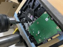
Harddisk replacement
Just repaired my desktop PC today by replacing the Seagate 3TB harddisk with a new one. The old disk stops spinning after a few seconds and something inside the harddisk makes a rattling sound. I have good daily backups and after restoring the data everything is running again as it was.
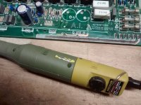
The drive was out of warranty. To make sure nothing can be restored from the platters of the dead drive I used my drill…
Safety first!
Regards, Gerrit
Just repaired my desktop PC today by replacing the Seagate 3TB harddisk with a new one. The old disk stops spinning after a few seconds and something inside the harddisk makes a rattling sound. I have good daily backups and after restoring the data everything is running again as it was.
The drive was out of warranty. To make sure nothing can be restored from the platters of the dead drive I used my drill…
Safety first!
Regards, Gerrit
Attachments
I'm so happy!
I found a set of Energy RC10 with a set of stands for 100$ CAD
I needed the tweeters to repair my RC70 -- Excellent speakers.
At this point, I have 4 extra 5 inch Energy drivers... Sub?
I found a set of Energy RC10 with a set of stands for 100$ CAD
I needed the tweeters to repair my RC70 -- Excellent speakers.
At this point, I have 4 extra 5 inch Energy drivers... Sub?
Repaired one Socket 775 motherboard. I mean changed el. caps, so it is hard to name as "repair". But I bought it as "crashes/freezes" so it can be named as repair.
I designed a simple ESR meter.
The circuit outputs a signal through a resistor then the signal goes into the capacitor under test. The output then goes into precision rectifier to catch the peaks of the signal.
This goes into a PIC a2d then onto PC via USB.
From this I can work out sum of Xc and ESR.
I wanted to just display ESR so changed my pc program to work out Xc then I can simply subtract it from total impedance seen. User has to input capacitance so I can work out Xc.
Today a Marshall EL84-20/20 stereo tube amp was on my bench. It was totally dead, the tube pcb desoldered, one xformer removed, all wires disconnected--
I was the second repair guy, the first one had given up after discovering a strong fire damage. This took place between two adjacent copper tracks at the edge of the pcb. Between them a black groove of burned epoxy showed up. You will not be surprised to learn that these copper traces carried both anode lines of the left channel. With a creeping distance of 1-2mm in between there is not much headroom for overvoltages or dirt. So I cleaned that area, removed the copper and patched 2 wires in transparent shrink tube instead. Checked the electrolytics, but these were fine. Found the schematics on the net and reconnected the loose wiring. A first test started with a howling noise telling me the power stage was oscillating. Reversed the phase of primary windings and now it is working again. Bias adjust should be set to 70mV accross the 1 Ohm cathode shunts. Anyway the max available is about 60mV, increasing the heat generation inside this superflat enclosure considerably.
Bad design imho, I am glad this is not my baby!
Attachments

Yo Bucks, I wonder if the fried channel had been driven hard into an open circuit at some point, maybe a disconnected speaker cable or something? A large back EMF in the OP's primary could explain the arcing between the traces?
Definitely not a good idea pairing up those 2 traces like that!
Definitely not a good idea pairing up those 2 traces like that!
Last edited:
I have seen back EMF reaching several kV when driven at resonant frequency of the output xformer in a 50W Marshall top even when connected to the speaker. Its rising impedance vs frequency is no guarantee for damping in the critical region above 5kHz. It took some effort to tame that beast. 😀
I have seen back EMF reaching several kV when driven at resonant frequency of the output xformer in a 50W Marshall top even when connected to the speaker. Its rising impedance vs frequency is no guarantee for damping in the critical region above 5kHz. It took some effort to tame that beast. 😀
That is why, in some older vintage tube amps, the designer used an appropriate capacitor(s), along with a resistor(s), across the primary of the output transformer.
To control/eliminate resonance issues.
I don't recall that discussed on here, however this is a DIY forum.
Motor driver IC.
Its 10 pins SIL.
I cut out old pins first then solder sucked remainder out of holes.
Some were a bit stubborn so had to try a few times with those.
Its 10 pins SIL.
I cut out old pins first then solder sucked remainder out of holes.
Some were a bit stubborn so had to try a few times with those.
Spent two hours doing a repair to the "junk drawer" in the kitchen.
Out of nowhere, the drawer front slanted down, causing the drawer to drop.
Apparently, the nylon roller that rides in the support track broke off.
The plastic of the drawer was snapped.
So I epoxied it back in place, lubed the roller with Super Lube, and added a metal strap over the top of the bearing assembly.
Works like a charm now.
- Home
- Member Areas
- The Lounge
- What did you last repair?