My whole house heating system.
Installed thermostatic valve on each heaters ( minus one still on/off valve as required), fixed the main boiler, rebuild the electrical distribution for it and changed the circulating pump.
I discovered my 4 way main valve is leaking... once everything was put into work again so it's only partially done/fixed atm.
If it doesn't get worse in the next few weeks i will wait until spring before any attempt to fix it though, as i don't want to go through the whole purge/reload/purge of each heaters again.
Now it's time to decide which kind of boiler will replace this old fuel based one as it won't last long. Hopefully it will stand the winter.
Last edited:
I am quite good at Central heating. I stay friendly with the local plumber. 🙂
I phoned him up one Cold Autumn when our central heating was doing nothing when I fired it up.
"Steve I am a bit busy right now. Fix it yourself. Electric pumps sit for 6 months of summer doing nothing. Therefore rust and clog up. Turn the screw on the pump. If that does nothing to clear it, buy a new one."
I did. £60 for a new pump. Had to tell a few lies about me being a Corgi registered boilerman for insurance purposes at our local supplier. But it ran like a dream!
Have been busy fixing a discarded chair I found up the street rotting in the rain. I bought a staple gun last week for £2. It's paying off already. That chair is above average on timber bracing and quality, IMO. Only issue is the seat is looking a bit stained and tired. Doubtless some disinterested workman used it for painting,
If Her Majesty the Queen was visiting my humble abode for Dinner, She might have "Concerns" about sitting on it. Nothing I can't fix with a Staple Gun and an Old Violet Pillowcase stapled to the wooden seat base! 😀
You can see my plan here. How hard can it be?
Attachments

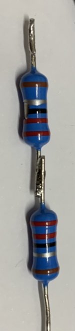
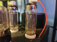
Resistors replaced
Just repaired my own tube amplifier. Two resistors of 2.2 Ohm in series both went into the megaohm range. The resistors were purchased less than a year ago and nothing strange is visible on the outside, except a damaged lacquer on the top resistor.
Only one tube of this channel was working correctly, but showing a high G2 current (KT150 tube, G2 glowing). These resistors were part of the cathode circuit.
With new resistors everything is OK again and both tubes work together as they should.
Regards, Gerrit
Attachments
The resistors are too small IMHO. They couldn't handle peak cathode current and opened. I would use 5W parts there. Also, you could consider making the screen stopper larger to prevent that much current from flowing in the screen circuit? Or make the screen resistor a smaller power rating to it will open like a fuse in the case of screen current.
I'm glad your KT150 still works. I had some 6550 that never worked the same after their screens lit up.
Question is, where did the screen current go? If the cathode was in the megohm range and the screen was glowing?
I'm glad your KT150 still works. I had some 6550 that never worked the same after their screens lit up.
Question is, where did the screen current go? If the cathode was in the megohm range and the screen was glowing?
Refrigerator condenser fan froze up resulting in the drip pan overflowing, which I discovered because it ran down the water inlet copper line and dripped on the dryer downstairs.
I sprayed the junction between the fan blade and motor body with penetrating oil. I also blew out all the dust bunnies with compressed air.
I am waiting to see if that is going to fix it or I have to buy a replacement fan motor, or option 3 buy a new refrigerator.
I sprayed the junction between the fan blade and motor body with penetrating oil. I also blew out all the dust bunnies with compressed air.
I am waiting to see if that is going to fix it or I have to buy a replacement fan motor, or option 3 buy a new refrigerator.
Hi Koda,
Only one tube was trying to do all the work (completely out of balance), that caused the screen to lit up. With max. 100 mA through a 2.2 Ohm resistor it’s only dissipating 0.022 Watt. The resistors should eat at least 1 Watt, probably 2 Watt without problems. G2 is fed from UL-tap with 1K2 10 Watt with 600 VDC B+.
Regards, Gerrit
Refrigerator condenser fan froze up resulting in the drip pan overflowing, which I discovered because it ran down the water inlet copper line and dripped on the dryer downstairs.
I sprayed the junction between the fan blade and motor body with penetrating oil. I also blew out all the dust bunnies with compressed air.
I am waiting to see if that is going to fix it or I have to buy a replacement fan motor, or option 3 buy a new refrigerator.
That must be a very old one. Please check power consumption, a modern one will be quiet and use way less power. RPM controlled compressor too.
Refrigerator condenser fan froze up resulting in the drip pan overflowing, which I discovered because it ran down the water inlet copper line and dripped on the dryer downstairs.
I sprayed the junction between the fan blade and motor body with penetrating oil. I also blew out all the dust bunnies with compressed air.
I am waiting to see if that is going to fix it or I have to buy a replacement fan motor, or option 3 buy a new refrigerator.
Curious, what brand of refrigerator, and how old is it?
Sounds like yours has an icemaker too, and everybody I know with that feature has problems with them.
My old 1985 GE fridge is still humming nicely with all its original parts.
And I don't mind filling up plastic ice cube trays, I've mastered the sink-to-freezer walk without any spills. 😀
CrosleySide by Side.
981kwh/year.
23 cu-ft.
1992?
I ordered a replacement referegerator and it should be in Wednesday.
Until then I have an extra fan blowing across the condenser coils.
981kwh/year.
23 cu-ft.
1992?
I ordered a replacement referegerator and it should be in Wednesday.
Until then I have an extra fan blowing across the condenser coils.
Last edited:
Hi Koda,
Only one tube was trying to do all the work (completely out of balance), that caused the screen to lit up. With max. 100 mA through a 2.2 Ohm resistor it’s only dissipating 0.022 Watt. The resistors should eat at least 1 Watt, probably 2 Watt without problems. G2 is fed from UL-tap with 1K2 10 Watt with 600 VDC B+.
Regards, Gerrit
Fair. I'm used to my sweep tubes that idle at 100mA but peak over 1A... I've blew up a few cathode resistors...
CrosleySide by Side.
981kwh/year.
23 cu-ft.
1992?
I ordered a replacement referegerator and it should be in Wednesday.
Until then I have an extra fan blowing across the condenser coils.
My understanding is if your Fridge or Freezer packs up, you leave the door closed to keep the cool in.
Failing that, disconnect from electricity, pour water over it and a point a fan at it. Water evaporating takes away the heat. 😎
An interesting last ditch solution about my newly-found discarded chair:
6 kg of wood. Worth £5 just burnt. 30 kWh! "Where there's Muck, there's Brass" as the old saying goes. Last time I met a scrap-metal man, he was driving a Rolls-Royce car. 😀
I visited last sunday my mother house. I repair my Old man car, you don't beleive it that i fix it in three days.
Fair. I'm used to my sweep tubes that idle at 100mA but peak over 1A... I've blew up a few cathode resistors...
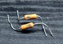
There are 1 ohm 2 watt Dales. I blew them with 6L6GA's running a little bit over spec. The tubes were not harmed and played just fine after replacing the resistors. Some over spec operation resulted in a tube arc. The blown resistors saved the tubes from a continuous arc which would have destroyed the cathode.
I have seen a similar arc resulting from a red plate runaway condition due to a gassy tube. Most new production tubes have a less that perfect vacuum which degrades faster than a well built older tube. This leads to increased grid current which upsets the bias leading to eventual runaway. Too much resistance in the control grid circuit exacerbates this problem. Pay attention to that spec.
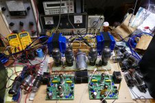
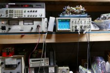
For those who may be interested the upper limit of a single pair of 75 year old 6L6GA's in AB2 is 112 watts. There is nothing glowing at this power level. This is a long time exposure, most of the light in the picture is from the pilot light on the power supply.
I replaced the resistor and tried it again. This time the other channel blew at about the same power level. I replaced the resistor again and listened to the amp for a few days before moving on to different tubes from my "junk" collection.
The last picture shows the setup with older 6L6G tubes. I tested them as well, but stopped when I saw 110 watts @ 2.6% THD since these are nice tubes and I didn't want to risk them.
These are all used tubes collected from various sources over 30+ years. The test conditions were as stated a bit over spec. B+ supply was 540 volts with cathode bias. There was about 525 volts on the plates of the tubes. The current meter on the power supply shows about 675 mA for all 4 tubes at 110 WPC. The OPT was 3300 ohms. Mosfet drive to the grids allows some serious AB2 with the control grids seeing +45 volts at the edge of clipping. Screen grid voltage was 300 volts.
Running some tubes in AB2 can get near sweep tube power levels, but for slapping the speakers around with authority, nothing beats the peak current capability of sweep tubes, and AB2 is not needed....or wanted.
Attachments


Spent three days troubleshooting the Carrier HVAC system in my new house. Got up the other morning and noticed the thermostat was off, no temperature and time displayed. There was no voltage at all. Broke out the manual and read it. There was an error #34, which can be a number of things. All the components checked out, but still no 24 Vac going to the thermostat. I checked every wire for continuity, then saw that one of the spade connectors on the sump pump for the evaporator was disconnected but sitting right next to the male end of the location it should have been attached to. Must have come off when I was sweeping around the pump, or maybe when I added some salt to the water softener brine tank? It only took 3 days to find the unplugged connector, right in time for the first frost scheduled for tomorrow...
A new valve amplifier where i hadnt spent enough time specifying transformers.
I use a mains transformer in to get 6VAC for heaters and then into a reversed mains transformer 9VAC to get 160VAC rectified B+ for valves.
For some reason I thought 6va was ok for second transformer as that what I used in a pre amp previously.
Of course my power amp requires much more current for the EL84's.
So had to cut out 6va transformer and replace it with a 25va transformer.
All is well now except the bodge to my pcb.
- Home
- Member Areas
- The Lounge
- What did you last repair?