Complete noob here. I've only done the ACA kit so far before trying this and that was pretty easy and went together with no problems.
I noticed smells and smoke when increasing the pot and it looks like my R29 and R32 are burning up. I'm pretty sure my PSU voltages are correct (around 16.9 for + and -). I've taken other measurements, but am not really sure what I am doing. I know that the 4N35 is supposed to regulate voltage to 1.2 and that should be detectable on those R29 and R32 resistors. The left channel, which seems to have no issues tests a constant voltage at R16 and R22 of .57 and -.53. But the voltages measured at R29 and R32 are much higher and moving around all over the place.
Anyone have a hint for where to look? Thanks in advance.
Attachments
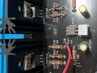
mosfet probably not isolated well. The D of the mosfet could get short thru the metal screw to the heatsink.
You are pulling a LOT of current through the output pair. Thats why the bias resistors are burning up. You appear to have the proper resistors in the area where we can see them.
Look for solder bridges, stray crumbs of wire, that kind of stuff on both sides of the PCB. Also make sure nothing is shorted to the mosfet screw.
Look for solder bridges, stray crumbs of wire, that kind of stuff on both sides of the PCB. Also make sure nothing is shorted to the mosfet screw.
I noticed the lid came uncomfortably close to shorting on the top of the heatsinks, so I went ahead and isolated them all. I was worried about minor lid flex causing shorts.
That is a potential cause. If you want the best cooling and don't want to use electrical isolation, you could possibly isolate the underside of the lid instead with tape.
That is a potential cause. If you want the best cooling and don't want to use electrical isolation, you could possibly isolate the underside of the lid instead with tape.
If the misfits are in the wrong spots you will have two forward biased diodes and burn those resistors.
If the misfits are in the wrong spots you will have two forward biased diodes and burn those resistors.
I suppose the mosfets in the wrong position would indeed be misfits 🙂
It is an IRF610 ….same I have in the kit. It is placed correct. I don't think we can see the cause of the problem in the picture.
The current draw seems not large enough to burn the primary fuse...….hopefully not a 30A as in my kit 🙂
When I fire my op I will either use a lab supply with current limiter or insert a primary fuse of type F which can deliver just what is needed and then use a vario trafo to slowly increase primary voltage so fuse is not burned by inrush. This way I can ensure that if something is wrong I don't burn components. When it works I can insert the correct T-type fuse in primary so it can take the inrush current during power on. Until now I have only burned a couple of fuses in my builds…….
What is "okay" for DC offsets? I've got no source hooked up, volume pot at 0, built from the DIYAudio store kit parts, other than using some 100uf/25V short Nichicon Gold electrolytic caps on either side of the opamp socket (to give more room for op amp rolling). I am getting +14.4 mV DC offset on both channels at the headphone out with the RC4580, and +18.8 mV offset with the LM833N. Are there any common mistakes made that would cause this?
I tried all 3 mentioned above. Got also very similar offsets (sub 20mV with LM833, fantastically low with AD823 and maybe a bit more than above mentioned with LM4562).
The offset depends on the devices used in the input stage of the opamp. JFET inputs will give lower offset. It is not a mistake in your assembly. You can adjust offset by modifying the resitors around the optocoupler. Look somewhere in the M2 threads.
I think people usually do not like offset higher than 10mV on their headphones, but it depends of the headphones as well. Some are also more adventurous than others.
It all boils down how much heat your headphones can take/you are comfortable with. Heat is power ie V * I.
I = V / R where R is your headphone resitance. V is the offset. How does this compare to the power your headphone producer claims in the specs?
I settled for AD823. Mainly because of the sound. Low offset came as a bonus. The old LM833 was surprisingly good soundwise as well. LM4562 was too bright for me after all.
I got:
0.4/0.6mVdc using a opa2107
2/3mVdc using LM833N.
So far i prefer the sound of opa2107, its quite clear in terms of transparency and texture. I ll soon also be comparing some other op amps like opa2156 opa1642 lme49720 49990 burson v6 vivid and classic. After my whole subjective assessment is done, i ll done some APX555 measurements (to avoid bias).
I got:
0.4/0.6mVdc using a opa2107
2/3mVdc using LM833N.
So far i prefer the sound of opa2107, its quite clear in terms of transparency and texture. I ll soon also be comparing some other op amps like opa2156 opa1642 lme49720 49990 burson v6 vivid and classic. After my whole subjective assessment is done, i ll done some APX555 measurements (to avoid bias).
Looking for your thoughts on the Burson V6 Classic and Vivid. I didn't think they had the same transparency as the 2107. But I haven't burnt either of them for more than 30 hours so I'm not sure if the 100 hour burn in would make a significant difference.
What is "okay" for DC offsets? I've got no source hooked up, volume pot at 0, built from the DIYAudio store kit parts, other than using some 100uf/25V short Nichicon Gold electrolytic caps on either side of the opamp socket (to give more room for op amp rolling). I am getting +14.4 mV DC offset on both channels at the headphone out with the RC4580, and +18.8 mV offset with the LM833N. Are there any common mistakes made that would cause this?
This isn't unusual due to the input bias current of bipolar opamps. 300 nA X 100K = 30 mV.
Hi Wayne and 6L6. Just a quick thanks for all your information on this forum. I finished my whammy a couple of months ago, and it sounds fantastic. I've started the new-to-me obsession with op amp rolling, as well as my first smd soldering. The differences so far are subtle but intriguing.
One thing I would share is that while I'm not a big component upgrade fanatic, over Christmas I found myself near Parts Express. On a whim I picked up two Jantzen Superior z caps, 1.0uf, for c1 and c5. From the moment I fired it back up with these caps, the difference was huge: top end now sparkles and the soundstage is incredibly broad and lifelike. Not sure if others have experienced this with different caps, but I couldn't be happier with the way it sounds. I'm using HD-650s and a variety of sources.
One thing I would share is that while I'm not a big component upgrade fanatic, over Christmas I found myself near Parts Express. On a whim I picked up two Jantzen Superior z caps, 1.0uf, for c1 and c5. From the moment I fired it back up with these caps, the difference was huge: top end now sparkles and the soundstage is incredibly broad and lifelike. Not sure if others have experienced this with different caps, but I couldn't be happier with the way it sounds. I'm using HD-650s and a variety of sources.
Interesting, I am using vishay film caps there.Hi Wayne and 6L6. Just a quick thanks for all your information on this forum. I finished my whammy a couple of months ago, and it sounds fantastic. I've started the new-to-me obsession with op amp rolling, as well as my first smd soldering. The differences so far are subtle but intriguing.
One thing I would share is that while I'm not a big component upgrade fanatic, over Christmas I found myself near Parts Express. On a whim I picked up two Jantzen Superior z caps, 1.0uf, for c1 and c5. From the moment I fired it back up with these caps, the difference was huge: top end now sparkles and the soundstage is incredibly broad and lifelike. Not sure if others have experienced this with different caps, but I couldn't be happier with the way it sounds. I'm using HD-650s and a variety of sources.
I use a jack connector which is not isolated from the chassis which means that output gnd will have chassis connection. Therefor I don't want e.g. input gnd connected also to chassis. But do I still want the small capacitor in the kit to go from input gnd to chassis/safety ground?
Plan is to start without and see how it goes…….
Plan is to start without and see how it goes…….
- Home
- Amplifiers
- Pass Labs
- "WHAMMY" Pass DIY headphone amp guide