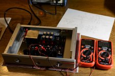
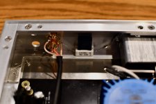
I fired up Whammy this night to check if everything seems to work as expected. I went for 7 (6.98) ohm bias resistors. The picture shows measurement of voltage drop over a bias resistor in each channel after 1/2 hour warm-up or so. 0.559V which is around 80mA bias current. Using the op amp from the kit (RC4580) which seems to have nice specs I have approx. 14 mV offset in both channel. Op amp is a BJT input type so some offset was expected. I had some sheet mu-metal on the shelf from M2X project so I wrapped the blue trafo with it. Next is to connect the connectors / pot. Will probably be done during the next few days.
Attachments
Last edited:
I run the very same bias resistor, and with the 22vac trafo the regs get very warm, despite my 30%bigger heatsink. I suggest keeping an eye on temos if running lower outputbias resistances.
Also the trafo goes a bit warm, so shielding it will increase temps, but it should be fine.
Also the trafo goes a bit warm, so shielding it will increase temps, but it should be fine.
My settled for about 54 C with open top. Will check later with top on when it is finished. Think it will be ok. The chassis is quite massive. 10mm front, 12mm side panels and top and bottom about 5mm. So it should be good at transfer heat.
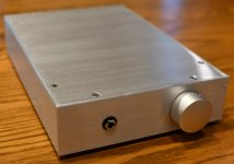
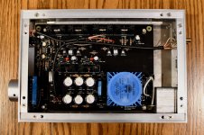
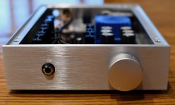
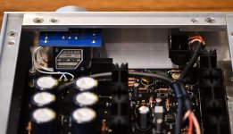
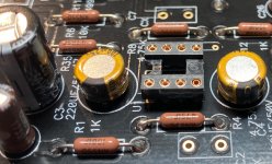
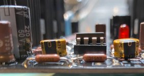
My WHAMMY build, mostly finished (for now). I used the DIYAudioStore.com kit purchased on Black Friday, and subbed a switched headphone jack so I can add preamp outs later that are enabled when no headphone is plugged in, and Nichicon Fine Gold 100µf/25v caps (suggested by @6L6 earlier in the thread) around the op-amp socket to leave more room for op-amp rolling (see the last 2 pics).
I used Mogami 2552 shielded mic wire for the RCA inputs -> board and board -> headphone out.
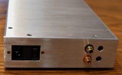
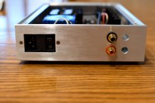
The safety ground is attached to the case via the screws pressing against the case of the IEC input jack. Since the case is currently bare aluminum, I didn't need to sand it anywhere to ensure solid connection. The RCA inputs are attached to safety ground via a ground loop breaker, paralleled 0.1µF cap/10Ω 5W resistor a la AMB M3 wiring.
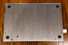
The chassis is from Landfall Systems. I machined the front, back, and bottom panels myself, which I am not entirely happy with my results using a drill press & coping saw - I may order some FPE panels to replace them. I got the brushed aluminum finish and it is way too easy to scratch it or leave fingerprints. You can see where I sanded around the IEC hole (it's a little brighter), because I scratched it in a couple places when doing final filing of the edges to get the jack to fit.
I still need to hook up the preamp out RCA jacks, and pick up some M3 screws/hardware to mount the board to the bottom panel. I'm using M4 hardware right now and my holes didn't exactly line up and so the board is a very tight fit on the M4 screws.
I left it on all day yesterday and took the top off to check temps, the regulator heatsinks were 70-75C and the 4 others were around 55-60C. I will probably add some ventilation holes to help lower the temps.
I'm enjoying it right now with a LM4562 op-amp and either Senn HD650 or Massdrop Hifiman HE-4XX, but it does seem a little bright. I've got some OPA op-amps to try next!
I used Mogami 2552 shielded mic wire for the RCA inputs -> board and board -> headphone out.
The safety ground is attached to the case via the screws pressing against the case of the IEC input jack. Since the case is currently bare aluminum, I didn't need to sand it anywhere to ensure solid connection. The RCA inputs are attached to safety ground via a ground loop breaker, paralleled 0.1µF cap/10Ω 5W resistor a la AMB M3 wiring.
The chassis is from Landfall Systems. I machined the front, back, and bottom panels myself, which I am not entirely happy with my results using a drill press & coping saw - I may order some FPE panels to replace them. I got the brushed aluminum finish and it is way too easy to scratch it or leave fingerprints. You can see where I sanded around the IEC hole (it's a little brighter), because I scratched it in a couple places when doing final filing of the edges to get the jack to fit.
I still need to hook up the preamp out RCA jacks, and pick up some M3 screws/hardware to mount the board to the bottom panel. I'm using M4 hardware right now and my holes didn't exactly line up and so the board is a very tight fit on the M4 screws.
I left it on all day yesterday and took the top off to check temps, the regulator heatsinks were 70-75C and the 4 others were around 55-60C. I will probably add some ventilation holes to help lower the temps.
I'm enjoying it right now with a LM4562 op-amp and either Senn HD650 or Massdrop Hifiman HE-4XX, but it does seem a little bright. I've got some OPA op-amps to try next!
Attachments
-
 1-front-angle.jpg621.7 KB · Views: 623
 -
 2-rear.jpg527.7 KB · Views: 612
 -
 4-bottom.jpg912.2 KB · Views: 612
 -
 5-overhead-open.jpg988.2 KB · Views: 555
 -
 6-front-open.jpg860.5 KB · Views: 292
 -
 7-back-open.jpg846.7 KB · Views: 245
 -
 8-front-jacks-wiring.jpg874.7 KB · Views: 247
 -
 9-rear-wiring.jpg682.3 KB · Views: 239
 -
 10-opamp-empty.jpeg788.9 KB · Views: 273
 -
 11-opamp-side.jpg583.6 KB · Views: 274
Last edited:
No need to buy new panels. If you want you can make the sanding more even if you demount the panels and work it with sandpaper in one direction until it looks "even". Nice solution with the low profile Nichicon caps. I used 150uF/25V Rubycon I already had which are smaller than the 220/50V in the kit. I have now enough space for a Burson type opamp and can pull up a normal op amp using a couple of pincets. I expect the Burson to be permanent in when it arrives.
I have made my Whammy a "Headphone only" even that I have mounted a switching type jack connector. To try out Whammy as preamp without RCA out it is possible to make a jack to RCA cable or buy one. Think I will do that for a quick preamp test in the future.
I have made my Whammy a "Headphone only" even that I have mounted a switching type jack connector. To try out Whammy as preamp without RCA out it is possible to make a jack to RCA cable or buy one. Think I will do that for a quick preamp test in the future.
The WHAMMY is a very nice preamp - in the right combination/chain of audio
equipment.
Different OPAmps make the WHAMMY 'adjustable' soundwise. 🙄
Have fun and try! 😀
Greets
Dirk
equipment.
Different OPAmps make the WHAMMY 'adjustable' soundwise. 🙄
Have fun and try! 😀
Greets
Dirk
Looking for your thoughts on the Burson V6 Classic and Vivid. I didn't think they had the same transparency as the 2107. But I haven't burnt either of them for more than 30 hours so I'm not sure if the 100 hour burn in would make a significant difference.
I have V6 Classic in Whammy for a few days now (less than 10hrs run)
I'll write up my impressions with pictures as promissed to Charles from Burson.
For now I'll say that Ad823 was my favourite (tried lm833, ne5532, opa2134, lm4562 and ad823 and opa627 from ebay-supposetly reclaimed so maybe not fake). Ad832 was pretty nice, but only with V6 I achieved musicality. Finally I listen to the music, not how good or bad the amp is.
The 18 Volt transformer will certainly lower the temps a bit if you need it and I have also used the 15 Volt version. Keeping things 60 C and lower is good practice but as an experiment I have done 100 C for a year and had no failures but wouldn't want that in production.
The 18 Volt transformer will certainly lower the temps a bit if you need it and I have also used the 15 Volt version. Keeping things 60 C and lower is good practice but as an experiment I have done 100 C for a year and had no failures but wouldn't want that in production.
You should go 3v lower for the voltage regulation, though, right, to make sure ripple and droop stays off the rails?
In data sheet the 78XX/79XX should have Thermal overload protection. Max. Tjunction seems to be 150 C. To test if device closes down before "self destruct" heathink should maybe be 125 C?as an experiment I have done 100 C for a year and had no failures but wouldn't want that in production.
In theory it should not be possible to destroy the device with "self generated" heat?

I only have the 78XX and 79XX sitting in my Whammy…...but I thought that Wayne's 78XX is setup for a possible destructive test.....so he could try 🙂
Of course it would be easy to install 78XX/79XX without a heatsink.....and then see what happens……
Think it should be self generated heat so device can decide to close down…..only then we can blame the device if it "goes south".....
Of course it would be easy to install 78XX/79XX without a heatsink.....and then see what happens……
Think it should be self generated heat so device can decide to close down…..only then we can blame the device if it "goes south".....
Regarding the Burson V6 Classic I asked if device could survive -+16.8V as it is what comes out of the regulators. Specification says max. -+16.5V. I got this answer:
"16.8V is right at the limit of what our opamps can handle. It could shorten their working life. If possible, please reduce it to 16.5V+-."
But given that device consumes 14mA and we have a 47.5 ohm serial resistor for each supply to the op amp the voltage drop just gets us on "right side".
"16.8V is right at the limit of what our opamps can handle. It could shorten their working life. If possible, please reduce it to 16.5V+-."
But given that device consumes 14mA and we have a 47.5 ohm serial resistor for each supply to the op amp the voltage drop just gets us on "right side".
My experience with protection is it usually works a microsecond too late.
Full disclosure one of my best friends nickname for me is smokey.
Full disclosure one of my best friends nickname for me is smokey.
Meper,
I suggest you drop the rails to the Burson V6s down to +/- 15 volts - they don't sound any better at 16v and, as mentioned, you're pushing their thermal limits and hence, useful life.
I run +/- 18v on the o/p transistors @ 120mA/channel (Salas Shunt Regs) but reduced this down to +/-15v for the V6s - works very well indeed.
14mA thru 47ohm resistor is a voltage drop of about 0.65V. That leaves you with +/-16.15Vdc to the OP amp. That's about 450mW dissipation for the OP amp.
With +/-15V rails it leaves you with about +/-14.35Vdc. that's about 400mW dissipation. So just over 10% reduction.
With +/-15V rails it leaves you with about +/-14.35Vdc. that's about 400mW dissipation. So just over 10% reduction.
I think I take the chance but will measure voltages to check if we are below -+16.5V. But a quick fix to get lower is to replace the 47.5 ohm resistors to maybe 80 ohm or so to have larger drop. If I knew up front I might have done it.....
- Home
- Amplifiers
- Pass Labs
- "WHAMMY" Pass DIY headphone amp guide