well, everything not electrolytic could be called "film" in this context
take any type, not being electrolytic
take any type, not being electrolytic

Hi!
There was an article from Pass labs which I can't remember anymore, explaining that these These cheap red Panasonic or Nichicon caps make a really excellent job as ground-coupling caps (if someone could point me to this doc, I'd be grateful!). You can find such caps in a lot of scrap electronics (TV's, old UPS, power supply boards...) The value itself is not important at all, it doesn't have to be 0.1uF. Really. I use whatever I find&salvage, with values ranging from .22 to .68uF. They will just act as a kind of spring/shock absorber between signal ground and chassis earth potentials, keeping both linked but still allowing them to move a bit when you compress them further.
However, for security reasons, I would highly recommend to use a 35A bridge between ground and earth and using the cap on top of that (see my build above). It will enable several amps to flow between ground and earth (enough to trigger your fuse or circuit breaker) in case a device connected to the input fails and high voltage appears on signal ground. This Nelson explains this very well in the Pearl II phono preamp article:
so, long story short: 1) Use another value instead of another construction type; 2) Use a 35A bridge for security purpose as well (it will not interfere with your cap, ad the diodes will block any current below 0.7V voltage difference between signal ground and earth.
There was an article from Pass labs which I can't remember anymore, explaining that these These cheap red Panasonic or Nichicon caps make a really excellent job as ground-coupling caps (if someone could point me to this doc, I'd be grateful!). You can find such caps in a lot of scrap electronics (TV's, old UPS, power supply boards...) The value itself is not important at all, it doesn't have to be 0.1uF. Really. I use whatever I find&salvage, with values ranging from .22 to .68uF. They will just act as a kind of spring/shock absorber between signal ground and chassis earth potentials, keeping both linked but still allowing them to move a bit when you compress them further.
However, for security reasons, I would highly recommend to use a 35A bridge between ground and earth and using the cap on top of that (see my build above). It will enable several amps to flow between ground and earth (enough to trigger your fuse or circuit breaker) in case a device connected to the input fails and high voltage appears on signal ground. This Nelson explains this very well in the Pearl II phono preamp article:
source: https://www.passdiy.com/project/preamplifiers/pearl-2 (last section)Also we see that the chassis is directly (and with heavy wire) attached to the earth ground of the AC line and that the signal ground of the circuit is attached to chassis through a high current bridge rectifier as shown.
The bridge is for safety purposes, and we use a standard 35 amp type to ensure that the AC line fuse breaks before the bridge. This avoids ground loops with the rest of the system sharing an AC line ground, while providing an electrical shunt above .7 volts in event of isolation failure. If you find that it lowers the noise, feel free to also connect chassis to circuit ground with a resistor, capacitor, or wire - but leave the bridge in for safety.
so, long story short: 1) Use another value instead of another construction type; 2) Use a 35A bridge for security purpose as well (it will not interfere with your cap, ad the diodes will block any current below 0.7V voltage difference between signal ground and earth.
Denis - thanks for your response.
I am a DIY soldering person, with little electronics experience and knowledge. I did some work 35 years ago at university, but as part of a mechanical engineering course. My big job here is building the case.
I like the bridge idea - can you please explain how I should wire it, as I can't see it clearly from the picture. Maybe a small diagram will help.
Thanks!
Next question from the newby:
The Nichicon 3300uF caps are out of stock, so I got the Nippon Chemi-con caps with very similar specs. They cost a few cents more as well and looks like the same quality in terms of build as the other Nichicon and Elna caps I got.
Does anyone have experience with the Chemi-con caps - especially in the power-supply section? Should I keep them for now and replace them once the Nichicons are available again?
For the power inlet, what size fuse is recommended? I have a Schurter DD12 inlet module. Leaving in Australia, so 220V.
xformer VA/mains voltage, then closest standard value
if pops (often) use first bigger
Chemi-con caps are good
if pops (often) use first bigger
Chemi-con caps are good
Zen Mod - so for 25VA transformer at 220V - that is 113mA. Closest I see at store is 160mA. Is that right?
I’m really digging the Sparkos dual opamp.I compared various opamps in Whammy, and preferred lme49720 till i tried burson. That is there till now.
yeah Chemi-con are good, I use them on several projects too. Just make sure they are rated at 35V at least. They don't need to be audio-grade, as their role is to filter the ripples of the DC power after the rectifiers and present a clean DC power to the LM7815/7915 regulators, which will then regulate the cvoltage to +15/-15V anyway.
I like the bridge idea - can you please explain how I should wire it, as I can't see it clearly from the picture. Maybe a small diagram will help.
I would make it a bit bigger, as significantly higher current than the standard 110mA-130mA will flow when you turn the amp on (all the caps need to be charged). You can safely use a 0.25A or 0,5A SLOW fuse. The aim is that if something happens in the transformer, the fuse blows before the circuit board or internal wiring. Provided that you didn't use 0.1mm2 wire between the circuit board and the IEC connector (ise at least 0.5mm2 or AWG18), a fuse with 0.5A slow rating will still be the weakest part that fails first. It's not a security issue to do it that way, you always have some headroom by a factor of +/-2 between the consumption of a device and the fuse rating.Zen Mod - so for 25VA transformer at 220V - that is 113mA. Closest I see at store is 160mA. Is that right?
btw, if you have shielding on your internal wiring (for instance if you run AC mains wires from the IEC socket on the rear to a power switch to the front), the shield must go to earth (chassis) ground, NOT signal ground.
Thanks! BUT, I am a slow learner here. In your drawing:
- Signal Ground - is the ground (or common) from the RCA inputs?
- Chassis Earth - is the the connection to the chassis or the earth wire from the main power inlet?
- Do I ground the metal body of the bridge to the chassis?
"Chassis Earth - is the the connection to the chassis or the earth wire from the main power inlet?" - to the chassis and the protective earth wire, so to both 🙂
Yes... you'll also see it referenced as audio GND around the forumView attachment 1194286
Thanks! BUT, I am a slow learner here. In your drawing:
- Signal Ground - is the ground (or common) from the RCA inputs?
You connect the mains earth from your power outlet to the chassis.... so it's both. You'll also see this called safety earth sometimes. It is vital that you do this.
- Chassis Earth - is the the connection to the chassis or the earth wire from the main power inlet?
You're not really grounding it. The metal plate is to help carry some heat. It doesn't electrically connect anywhere.
- Do I ground the metal body of the bridge to the chassis?
Apologies for my low level of knowledge here.
Almost there, thanks for your patience.
Do I connect the signal ground to both the Neg and Pos positions and the earth to both the other ports?
Thanks again.
Do I connect the signal ground to both the Neg and Pos positions and the earth to both the other ports?
Thanks again.
Signal Ground - is the ground (or common) from the RCA inputs? => yes, which is also connected to the ground of the "phones" output.
Chassis Earth - is the connection to the chassis or the earth wire from the main power inlet? As SomekPoland wrote, it is attached to both, and that's the point: the enclosure of the device must be linked to earth, so that if any voltage appears here for whatever reason, the current can flow UNHINDERED into earth instead as flowing through your body if you touch the case. The easiest is run a (heavy!) wire directly from the IEC plug to the chassis using a ring terminal that fits under one of the screws that holds the chassis panels together. And from that screw you run another (heavy) wire to the bridge rectifier as in my drawing.
Do I ground the metal body of the bridge to the chassis? You can, but there's absolutely no point of doing so (not even a tiny bit). The metal body of the rectifier is isolated from the 4 terminals ( AC, AC, +,-). Its sole purpose is for heat transfer. Remember that it is rated at 35Amps, designed to operate at such high currents constantly (24/24 7/7)! In such an application, the bridge needs adequate, massive heatsinks to dissipate the energy from the diode losses. In our case however, we use a 35A bridge only to make sure the bridge won't break before your house's AC mains circuit breaker triggers. It will be a very short surge, and the bridge won't get any warmer, not even a hundredth of a degree. And the most probable case is that this situation will never happen anyway if the amp and the devices connected to it are built properly. It's just a security device, what will propably never be used.
my pleasure! Glad if I can help!Almost there, thanks for your patience.
Do I connect the signal ground to both the Neg and Pos positions and the earth to both the other ports?
both AC terminals are connected together and go to chassis ground (the connection between both terminals must have the same wire gauge as the rest of the cable! Pos and Neg are connected together and go to signal ground (same wire gauge).
then, you connect your red cap between one of the AC terminals and one of the DC terminals (Pos or Neg, it doesn't matter since there are interconnected thanks to your wire).
Don't hesitate do post a pic here once you have done it so we can validate your wiring if you're not sure. This is a potentially life-saving circuit that must be done the right way.
Hello guys. I am getting a squealing noise when I turn the Whammy off. It's very bad and loud (more like a shrieking sound) with OPA627, but it makes a very quiet squeal with LM833N op amp. I've attached a picture of my build. I have a blue LED power indicator light installed. All LED's do not turn off right away when I turn the Whammy off, wondering if this has something to do with it.
Attachments
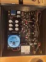
Hi, when you say you use the OPA627, I hope you did not just put that OPamp in the sicket, but used an adapter for 2 opamps instead?
Because the OPA627 is a single, it can't work if you just plug it in the existing socket instead of the LM933N, which is a dual opamp!
It's absolutely normal that the onboard leds take time to fade out (even at different rates), it is the time it takes for the 6 PSU caps to drain...
Because the OPA627 is a single, it can't work if you just plug it in the existing socket instead of the LM933N, which is a dual opamp!
It's absolutely normal that the onboard leds take time to fade out (even at different rates), it is the time it takes for the 6 PSU caps to drain...
- Home
- Amplifiers
- Pass Labs
- "WHAMMY" Pass DIY headphone amp guide