I'm getting close to the finish line, and I have a couple of questions.
What is the preferred order for the mounting hardware for the RCA jacks? For now, I'm assuming this order would be preferred (most outside to most inside):
nut
flat insulator
rear panel
shoulder insulator (shoulder drops into panel hole)
solder lug
nut
I can't find the instructions for wiring the power LED that goes into the front panel. Is it supposed to tap into the AC of the transformer secondary, or is it supposed to tap into the V+ DC?
Also, I still haven't seen a response to my query (in post 4799 above) about the fuse rating.
Thanks,
Gary
I don't think you have the order quite correct. It is likely ...
Outside of amp
Jack
Insulator
Rear Panel
Insulator
Ground Lug
Nut
Nut
See step 5 of the ACA guide as a reference for lovely pics of an example.
https://guides.diyaudio.com/Guide/Amp+Camp+Amp+V1.8+Change+Information/10?lang=en
re: LED. No it does not come off the AC secondary. There are a few places you can get the DC voltage. Search this thread for multiple good ideas. If that doesn't produce results, shout. I'm not familiar with the PCBs or whether a current limiting resistor was included in the kit and/or where it should be installed.
re: the fuse. 2A seems like a lot for a WHAMMY. Perhaps someone can chime in re: what is intended to be included with the kit. Nice catch and kudos to you for not randomly installing components w/o asking when you have a concern.
Fuse rating will depend on the VA of the power transformer. Fuse Ampere rating = VA/(Wall AC Voltage)
Theoretically the LED may be powered by AC or DC, although most builders power the LED off the power supply output as it is handy for indicating a functioning power supply.
Theoretically the LED may be powered by AC or DC, although most builders power the LED off the power supply output as it is handy for indicating a functioning power supply.
If it's from the kit, the Talema transformers previously provided were 15VA. 2A is ... too much... to me. Not sure what's intended to be in the kit.
I suppose I could have mentioned the theoretical AC power option for the LED. Good call.
I suppose I could have mentioned the theoretical AC power option for the LED. Good call.
Thanks to y'all for chiming in.
@ItsAllInMyHead, in looking at all of the photos I could find that clearly showed the order of parts, they were fairly evenly divided between the folks who chose to put 2 nuts "back-to-back" (inside), and those folks who put one outside and one inside. I guess that it doesn't really matter except for cosmetics (while making sure that the shoulder washer is next to the panel).
I need to find and re-read the discussion of tapping into the AC for the LED.
As for the fuse, I'm using the full kit, so the transformer has the 22v secondary. If I remember correctly, some of the older comments mentioned approx 0.5A SLOW blow fuse, while the one in my kit was 2A FAST blow.
Double nut inside with second nut as a lock nut.
Transformer is Talema 70064K 115V/230V transformer according to the diyAudio Store Whammy Completion Kit webpage. Digikey shows 25VA for the transformer, so 25VA/115V = 0.22A, so 0.25A fuse and slow is fine.
Power supply schematic shows 15V bipolar power supply. The easy Led hookup is a 15k to 20k or so resistor in series with the Led and connected to the power supply output. If connecting to +15V, connect the resistor to +15V, connect the Led anode to resistor, and connect the Led cathode to power supply ground.
V+ output is at C9, so resistor and Led can be connected to C9. Capacitor plus is +15V, and capacitor negative is ground.
Last edited:
Sometimes I prefer the LED to respond immediately, when the power switch is changed from on to off. Rather than watching it sloooooowly fade out as the DC power supply gradually discharges. In those cases I use a simple circuit with only 3 components (LED + current_limit_resistor + part3), connected to the transformer secondary's AC voltage. When the power switch is flipped to OFF, this LED's current falls to zero in less than 8 milliseconds. Less than one frame of a motion picture in the cinema: (1 / 24 FPS == 42 milliseconds)
The circuit is discussed in post #1530 of this thread.
The circuit is discussed in post #1530 of this thread.
@Mark Johnson, thanks for the pointer to the discussion of tapping into the transformer secondary. That was what I knew I had seen, but had forgotten where!
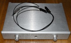
I have a quick question regarding the cable I built when using the Whammy as preamp.
Normally you like to have a 50R resistor to the RCA output. This can make the output more short circuit proof and also it should prevent oscillation in a capacitive load?
Now I made a straight cable long time ago without any 50R resistor. The cable is short as the picture shows but was it a design error regarding the oscillation or is the Whammy design robust regarding this?
I have had no trouble when using the cable. So it seems to work fine.
Attachments
I never made RCA or XLR cables with internal resistor
except in few specific cases, when I needed L attenuator cell inside the cable
if you need that (series resistor or any other gizmo inside the cable) to ensure upstream or downstream component behave - you're in problem - that component is not well designed
Wayne's work is flawless, be sure of that
except in few specific cases, when I needed L attenuator cell inside the cable
if you need that (series resistor or any other gizmo inside the cable) to ensure upstream or downstream component behave - you're in problem - that component is not well designed
Wayne's work is flawless, be sure of that
Does someone have the part number for the Blue LED on/off indicator that comes with the kit?
Also the two regulators are sold out everywhere, does anyone know an alternate part I can use instead or does anyone have spares I can buy from them?
Also the two regulators are sold out everywhere, does anyone know an alternate part I can use instead or does anyone have spares I can buy from them?
Last edited:
I don't know what exact LED is in the kit but here is a 3mm blue LED: 3mm blue LED
If you are referring to the 7815 and 7915 regulators, here are some: 7815, 7915
If you are referring to the 7815 and 7915 regulators, here are some: 7815, 7915

da9520, the information you are seeking is posted on the Whammy Chassis page: https://diyaudiostore.com/collections/whammy-headphone-amplifier/products/whammy-chassis
Does anyone know if the Whammy power supply have enough current to use the Sparkos SS2590 pro opamp?
- Home
- Amplifiers
- Pass Labs
- "WHAMMY" Pass DIY headphone amp guide