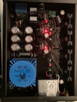
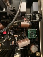
Here are some pics he sent me. Let me know if you need more. First time he said it was fine for 30 minutes then it started to make a noise. He turned it off and after running it the second time it was fine for 9 minutes
Attachments

@da9520
Just let the Whammy run without the lid, the rest screwed together, of course, so that there are no short circuits.
You installed the 2 x 22V transformer. The 7815/7915 with the original heat sinks can get very hot in a closed housing, which means that all other components can also heat up very much.
Does it have the 0.1uF bypass caps across V+/V- and ground? Most opamps specify for one in their datasheet, I know Sparkos specified it's required.
An evening with the WHAMMY, a review, will be available soon at Ear-Fidelity.com.
Config:
iFi Audio iDSD PRO Signature
WHAMMY + opamps: MuzgAudio, Stacatto Audio and Burson V6 Vivid
HiFiMan HE6SE
Denon AH-D9200
Sennheiser HD800
Well, what I can tell..? It is a fantastic amplifier which can drive even demanding headphones with ease. Sound is amazing, full, natural, and great sound staging. Kicks *** of most commercial amps at its price range and not only. When you add discrete opamps it gets even better, but even stock: fantastic amp.
The assembly was pretty straightforward, although there were some small mistakes in the guide (eg. where to connect the power LED). Nothing I couldn't handle, but I met a guy on Facebook who got stuck with his WHAMMY.

I’m about to finish up my Whammy, I hate doing jacks and AC, boring 🙃 I used a tapered counter sinking bit to reveal some bare metal on the inside of the ModuShop chassis faceplate to get a good contact with the pot bushing and added a thin star-nut around the collar too, should be good but from the start I was suspicious of the ModuShop chassis. The anodizing was done after all the drilling and tapping, and the bolts are all black too.
When I first got the chassis I bolted it up and tested if I could get continuity between the panels: top, bottom, front, back, sides, I couldn’t between any of them. Tested from bolt to bolt, plus anywhere I thought the anodizing might be thin, like inside the screw holes and in the rails where the little top and bottom plate nuts slide. I also cut away material on the outside of bottom plate ground hole with the counter sinking bit so as to use a flat head countersunk bolt for a good ground connection. Still, probing from this now reliable ground point to the metal parts of Alps mounted in the faceplate and any of the other panels I could not get continuity anywhere.
As far as I can see the only part of the ModuShop chassis that is providing shielding is the bottom plate. Nothing else connects to ground including the pot case and shaft which will have a metal knob. So, not the safest thing, granted it would require an exceptional fail to get AC or DC on the pot, like someone pouring Gatorade inside, but still, a metal knob should be grounded.
I read through the 240 pages a bit at a time a long while back, I don’t recall anyone bringing this up. It’s a very snazzy chassis I don’t really want to risk a Dremel grinding wheel near it to rough up spots where the panels meet, too easy to nick a visible part plus the risk of metal dust and shavings around the silk screened faceplate and back.
I left this conundrum for later but now later is here. Has anyone tried to deal with this? What did you do?
The surface finish is not conductive, so you should remove it where parts meet (not the whole length of course. This is the only way for having conductivity to every part of the chassis.
I've encountered anodizing before but never on something I was scared to scratch up. I was hoping to avoid reptile dentistry and someone had a simple solution. I have a hand reamer I think I'll try cleaning up one screw hole on the inner side of each panel and see what happens. I don't think the screws are painted, just blackened steel, they seem to be conductive, enough anyway. I decided I need to deal with the chassis before booting up, if there's any hum it'll rain on my parade, and worse I'll wind up going down blind alleys trying to troubleshoot it.
Sure, fingers crossed for a successful maiden flight. I still haven't done that (and I need to change a few other things), but it works flawlessly even now.
Quick report on the chassis continuity issue. I previously tested the chassis all bolted up except for the top plate, that just sat in place and I probed through the screw holes into the nuts in the tracks. When I put the chassis away last I screwed in the top plate to not lose the screws, today before taking a reamer to it I probed the chassis one more time to try and determine the best holes to ream, and surprisingly I had continuity between all the panels except for the back, even to the Alps casing. So, the little screws and nuts for the top panel must be biting into the side panels and the top, which is good and solves 90% of the problem. For the back panel I gently reamed out the four screw holes from the inside along with one of the Schurter IEC mounting holes that I will use for the ground cap and got continuity there too. BTW you can check the top and bottom plates for continuity, to be sure it’s not just the steel screws making contact with the sides, by sticking one probe into the vent slots at an angle with careful pressure, apparently the anodizing is thin there. So, all good now, almost ready for power up.
Hope this helps someone, and if you have the same problem don’t use a Dremel or file, the proper tool is a reamer like this one, it will scrape the anodizing on one side only:

Hope this helps someone, and if you have the same problem don’t use a Dremel or file, the proper tool is a reamer like this one, it will scrape the anodizing on one side only:
Max output current while remaining in Class-A operation, is 2x the DC bias current. Post #2 of this thread shows the DC bias current and if you like, you can interpolate the data.
If you drive it harder, Whammy will supply yet more current -- but now it will be in class-AB.
If you drive it harder, Whammy will supply yet more current -- but now it will be in class-AB.
Last edited:
Friends!
We are excited to share my review of the Whammy. Feel free to ask questions if you have any 🙂
https://www.ear-fidelity.com/whammy-review/

We are excited to share my review of the Whammy. Feel free to ask questions if you have any 🙂
https://www.ear-fidelity.com/whammy-review/
By changing the ratio of R8/R12. Please look up Inverting operational amplifier gain. What do you need the extra gain for?Hi everyone
how can I adjust for max gain for this amp ?
Is it to drive F4 as @Oracle1 mentioned? If that's the case, then you will lack the necessary voltage headroom. You would have to get an opamp that can do +/-24V rails, and change the power supply accordingly.
I'm sorry to be asking a basic question, but I don't know how to search for "impedance" and only get results from this topic.
I would like to build a WHAMMY to drive my Yamaha HP-1 headphones which have a 150-ohm impedance.
Thanks!
I would like to build a WHAMMY to drive my Yamaha HP-1 headphones which have a 150-ohm impedance.
Thanks!
just go for it
WHAMMY is capable of driving much tougher ones ( having lower impedance)
WHAMMY is capable of driving much tougher ones ( having lower impedance)
As I've read through the messages (I'm up to page 110!), I've seen a variety of recommendations for the fuse type. The one that was included in my kit was 250v 2a fast blow, but I've seen several mentions of 1/2a slow blow.
Also, is there a magic way to open the fuse drawer. I've opened it twice and it seemed like I was deforming the plastic a bit.
Also, is there a magic way to open the fuse drawer. I've opened it twice and it seemed like I was deforming the plastic a bit.
- Home
- Amplifiers
- Pass Labs
- "WHAMMY" Pass DIY headphone amp guide