OK, I changed from the LED voltage reference to the naked regulators so that I can run different op-amps. I desoldered the volume pot and tested it. It tracks perfectly. I then changed my 4580DD op amp to a LM833N and then to a OPA2134PA. With volume turned to zero and no input or output, I measured the voltage across R16, R22, R29, and R32. It was constant at 0.5642, 0.5644, 0.5604 and 0.5644. The left channel was still louder than the right. Finally, I desoldered the DIP-8 socket and replaced it with a spare. My Whammy is now perfect! Thank you so much for everyone who offered advice. I pretty much read through all 233 pages of the guide. The Whammy is awesome!1. Check all resistor values.
2. Solder Opamp directly into the board. Do not use dip adapter.
3. Check the Alps RK27. It might have channel imbalance.
Piete5

About DIP sockets: I've never had any problems with the gold plated four finger collet socket designs. It's the single contact surface types are definitely to be avoided.
Got a Mouser or Digikey link? One for the "good" and one for the "bad"? (and maybe one for the ugly? 🙂)About DIP sockets: I've never had any problems with the gold plated four finger collet socket designs. It's the single contact surface types are definitely to be avoided.
Got a Mouser or Digikey link? One for the "good" and one for the "bad"? (and maybe one for the ugly? 🙂)
Maybe this?
110-43-308-41-001000
or this
110-13-308-41-001000
There used to be a type of socket that had a single pin conductor come up into the socket and bend back down again to create a spring tension against one side of the IC pin. Those kind are long out of production but can still be found in junk boxes, parts bins and old equipment. The modern ones that are still less than ideal have a single conductor that comes up bends down and then up and down again to put tension on two sides of the pin. The modern Milmax ones that slk23 mentioned above have round pins instead of flat ones and has a collet that has tension contacts on 4 sides of the IC pin. They work great and you can even stack them for added height if using large discrete op amps that need extra clearance from the board.
I recently completed a build of most recent version of Whammy with all components from DIY Audio Store. I used the build guide that was linked from that site. Initially I was getting low volume from right channel, particularly voices. I've looked over the board, don't see any errors. Now I realize there is significant crosstalk from left to right channel, but not the other way around. Any ideas where the problem may be?
Connect to only one input jack at time. Perhaps that will help understand the problem.I recently completed a build of most recent version of Whammy with all components from DIY Audio Store. I used the build guide that was linked from that site. Initially I was getting low volume from right channel, particularly voices. I've looked over the board, don't see any errors. Now I realize there is significant crosstalk from left to right channel, but not the other way around. Any ideas where the problem may be?
I have the whammy complete kit with oversized black case. I monitored the internal temperature with an I2C sensor. After one hour of idle operation the temp. was more than 49C. This is not terrible but it is too much for my liking. I am guessing that a Whammy with a 2x22vac toroid in an unvented case would be much hotter.
Regulators become stressed when the output volts is much lower than the input. With a 2x18vac toroid, mine has a drop of 28-17=11vac. I need to replace the Amveco 70064 toroid with 70053 15vac. The Amveco version is obsolete.
The schematic has OPA2604 which has 15v max power supply. Lifted regulators will exceed it's absolute maximum.
My kit came with JRC4580. It has a maximum of 18v so it is safe except for the 21v version of regulator setting.
LM4562 has maximum +-17v. NE5532 maximum is +22v
It is necessary to raise the regulator output volts or use a reasonable torid secondary output so that high temperatures don't run amok. I prefer to not operate components at their absolute maximum. They should have some wiggle room.
I think the higher voltage after the regulators (+/-18V) is desirable for the MOSFETs and overall power output/drive capabilities. It is undesirable for the OPAmps... the JFET input ones (that would allow for DC sound path coupling. i.e. no capacitors) usually like to see no more than +/-12 ... maybe +/-15 V top.
If I were to make one of these kits, I'd add LT3054/LT3095 voltage regs to drop the rails down from +/-18V to +/-12V and then use my favourite OPAmp AD8066. That would be okay for the LT regs as well - they wouldn't need any heatsink due to a very low OPAmp current consumption.
Not to mention the very low noise environment established... for the OPAmp.
I recently completed a build of most recent version of Whammy ... Initially I was getting low volume from right channel, particularly voices. I've looked over the board, don't see any errors. Now I realize there is significant crosstalk from left to right channel, but not the other way around. Any ideas where the problem may be?
Please post a series of well-lit, in-focus photos and we can start the debugging process.
🙂
I took another good hard look and spotted the error. I reversed ground and left channel on the HP jack,I connected the other side going to the RCA out correctly, go figure. Anyhow, seems to be working great. Found it when I was tracing left channel through the ckt, Thanks again.
Not as bad as what I did a while back: Hooked up the power backwards to a B1. Fried the filter caps completely.
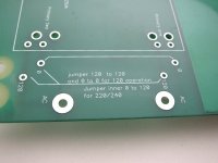
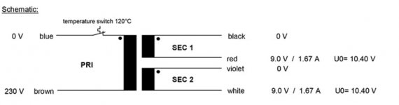
Hi Everyone, I am trying to modified the Whammy Kit from original Talema Transformer to Primary 230V Transformer. As the primary voltage of new transformer is 230V only, how should I solder the transformer in the pcb? And How should I solder the jumper? Thanks.
Attachments
Hello;
I would like to add a second RCA input rather than an output on my whammy. I was looking at building one of the diykits to stuff in the chassis, and then realised a dpdt throw should work fine.
Am I correct, or do I need to rethink this plan?
I would like to add a second RCA input rather than an output on my whammy. I was looking at building one of the diykits to stuff in the chassis, and then realised a dpdt throw should work fine.
Am I correct, or do I need to rethink this plan?
Should be perfectly fine. If you want to isolate the grounds, use a 4PDT switch, but most people don't bother, from what I can tell.
Does anyone know the part number for the LED that comes with the complete ehammy kit? The one that is supposed to mount through the face plate? Either mine arrived dead, or I am crap at following instructions and killed it, or I am crap at following instructions and wired it wrong. regardless; I need a resistor for it (20k?) and another LED to try, and some 27 ohm resistors to try the rca out.
Someone can correct me, but I'm pretty sure the flat top blue LED is something very much like this:Does anyone know the part number for the LED that comes with the complete ehammy kit? The one that is supposed to mount through the face plate? Either mine arrived dead, or I am crap at following instructions and killed it, or I am crap at following instructions and wired it wrong. regardless; I need a resistor for it (20k?) and another LED to try, and some 27 ohm resistors to try the rca out.
https://www.digikey.com.au/en/products/detail/tt-electronics-optek-technology/OVLLB8C7/827137
Which you can also get in a few other colours:
Yellow:
https://www.digikey.com.au/en/products/detail/tt-electronics-optek-technology/OVLLY8C7/827140
Green (my preference):
https://www.digikey.com.au/en/products/detail/tt-electronics-optek-technology/OVLLG8C7/827138
Red:
https://www.digikey.com.au/en/products/detail/tt-electronics-optek-technology/OVLLR8C7/827139
If your multimeter has a diode mode you can test they are alive and well before popping them in. The diode mode is gentle enough that it generally won't kill an LED even if you get the polarity wrong, so you can also use it to check polarity if you're not confident of other methods.
EDIT: Or was the original white? I'm not sure - I didn't use it!
Last edited:
- Home
- Amplifiers
- Pass Labs
- "WHAMMY" Pass DIY headphone amp guide