does anyone have a DXF file of the mounting holes for the PCB? Im looking to use my CO2 Laser and 3D printer to make a new housing for my Whammy. Thanks
I received a Whammy Kit from the DIYAudioStore. I received 4 x 220uf 50v and 2 x 220uf 25v. I read you can use 25v but never thought you could mix and match them. Is this ok or should I get a replacement?
Mixing isn't an issue, so long as the power rating is high enough (though you'd presumably want to used matched parts in different channels, where relevant). But you probably want to use the 50V ones for C8,9,10,28 in the power supply, and the 25V ones as the bypass capacitors C3 and C4. They should not see more than the regulated 15V in practice. (Then again, nor should the others, but they're closer to the regulator.)
Hello all. I'm slowly working on my new Whammy kit (power section done and working so far), and am wondering if people could help me collate here the things that have changed between the publication of the build guide and the new full kit, so that I know which things I need to investigate for myself outside the guide.
So far I know:
And that's about all I've come across so far. What other differences am I likely to encounter as I complete the kit? Any recommendations?
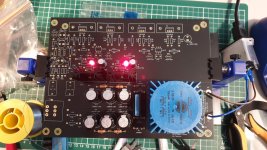
Anyway, here's mine so far. I'm enjoying it, albeit in small bursts when parenting allows.
So far I know:
- the Modushop Galaxy case provided is obviously different to the Hammond used in the original, and so assembly differs (this one is no biggy - I'm sure I'll figure it out)
- the kit now has a status LED and a hole in the faceplate for mounting it (I've seen some have wired this to R9 & R10 with an appropriate resistor)
- the kit now has a pre out (I have not yet investigated how this should be wired)
- as just mentioned by jimmyc23 above, the kit now has 2x 25v 220uF caps (for C3 & C4, I assume to provide better clearance for rolling larger op amps)
And that's about all I've come across so far. What other differences am I likely to encounter as I complete the kit? Any recommendations?
Anyway, here's mine so far. I'm enjoying it, albeit in small bursts when parenting allows.
Attachments
Yeah, more similar than different. Just make sure you find a spot for connecting your earth and ground. Scan through some of the photos of people's builds to get some ideas of where you may want to connect everything in a "star" configuration.
- the Modushop Galaxy case provided is obviously different to the Hammond used in the original, and so assembly differs (this one is no biggy - I'm sure I'll figure it out)
Not sure if the PCB layout has changed or not. I ended up just connecting my power LED to one of the big capacitors in the PSU bank and hooked up a resistor in series to limit the current. Only downside is the LED doesn't turn off immediately (takes a couple seconds or so), but is a simple solution.
- the kit now has a status LED and a hole in the faceplate for mounting it (I've seen some have wired this to R9 & R10 with an appropriate resistor)
Not sure if the PCB has changed to accommodate one, but the chassis does indeed offer cutouts for a pre-out. What most folks do is wire that up to your headphone output jack -- usually the Neutrik switching jack so that when you unplug your phones, it routes the output to the pre-out, and vice versa.
- the kit now has a pre out (I have not yet investigated how this should be wired)
Correct, you'll probably want a little bit more room there near the opamp socket for rolling.
- as just mentioned by jimmyc23 above, the kit now has 2x 25v 220uF caps (for C3 & C4, I assume to provide better clearance for rolling larger op amps)

@twofires
If you want to have lots of room around the socket for trying discrete opamps and such, you can bottom-mount the two electrolytic caps flanking the socket.
Here are some photos to help answer your questions -

LED can attach here. The LED current resistor is attached to the LED and covered by heat shrink in these photos. Use anyting from 15K-30K depending on how bright you want it.


The line out can be directly attached to the RCAs from the headphone jack, but it’s a good idea to add some low-value build-out resistors so the output is always looking into a little resistance when nothing is plugged in. These are 27ohm. Anything between 15ohm and 47ohm will work perfectly.


And a couple of overview shots in the new chassis.
If you want to have lots of room around the socket for trying discrete opamps and such, you can bottom-mount the two electrolytic caps flanking the socket.
Here are some photos to help answer your questions -
LED can attach here. The LED current resistor is attached to the LED and covered by heat shrink in these photos. Use anyting from 15K-30K depending on how bright you want it.
The line out can be directly attached to the RCAs from the headphone jack, but it’s a good idea to add some low-value build-out resistors so the output is always looking into a little resistance when nothing is plugged in. These are 27ohm. Anything between 15ohm and 47ohm will work perfectly.
And a couple of overview shots in the new chassis.
Last edited:
@twofires
If you want to have lots of room around the socket for trying discrete opamps and such, you can bottom-mount the two electrolytic caps flanking the socket.
Here are some photos to help answer your questions -
View attachment 1083742
LED can attach here. The LED current resistor is attached to the LED and covered by heat shrink in these photos. Use anyting from 15K-30K depending on how bright you want it.
View attachment 1083744
View attachment 1083745
The line out can be directly attached to the RCAs from the headphone jack, but it’s a good idea to add some low-value build-out resistors so the output is always looking into a little resistance when nothing is plugged in. These are 27ohm. Anything between 15ohm and 47ohm will work perfectly.
View attachment 1083746
View attachment 1083747
And a couple of overview shots in the new chassis.
That's excellent - thank you very much for all that.
Two quick questions:
1) So the input shield is grounded, and the ground follows the signal through to the headphone jack, and from there to the preout jacks? I was wondering before I saw your photos of all the rcas were grounded together, but I'm guessing that would cause hum and other problems I don't yet understand?
2) Is there anything I should or could do with the switching headphone jack to prevent pops or other signal issues when unplugging headphones? I plan to use the Whammy for headphones, but also as a pre for a pair of ACA. Or is the best policy to disconnect the headphones before the power amps are on?
Thanks again.
There's only one ground ultimately. Many people do just tie the grounds from the RCAs together right there. You can also run separate wires if you prefer, or do some kind of 'star grounding' thing.Two quick questions:
1) So the input shield is grounded, and the ground follows the signal through to the headphone jack, and from there to the preout jacks? I was wondering before I saw your photos of all the rcas were grounded together, but I'm guessing that would cause hum and other problems I don't yet understand?
It's best to do that with the amps off. But in the B1, there are 1M resistors between the inputs and ground just in case someone should decide to connect or disconnect inputs while the amps are on. I would suppose you could do something similar here.2) Is there anything I should or could do with the switching headphone jack to prevent pops or other signal issues when unplugging headphones? I plan to use the Whammy for headphones, but also as a pre for a pair of ACA. Or is the best policy to disconnect the headphones before the power amps are on?
Riki
Exposing my ignorance… I want to roll some op-amps. I have the stock kit up and running nicely. I’m currently using the LED + capacitor version on the voltage regulation circuit. I have NOT measured the Vcc+/Vcc- at the op-amp socket so I don’t know what those numbers settled in at… I know it will be regulator output (+/- 15) + the voltage set by the LED, presumably something just less than 18V
1. For op amps that have |Vcc| max at 18V, do I just run them at the bleeding edge or…
2. Could I put a ‘switched’ jumper in at R9 and R13 (shorting them) to toggle between the LED reguated voltage and +/- 15V?
Is there a negative consequence to leaving in the cap and the LED in the circuit while trying to run at +/- 15V? Electrically, I understand that both sides of the LED and Capacitor are now at ground (with the jumper in place).
I apologize if this has been answered elsewhere.
Ryan
Last edited:
Sadly there are some very appealing dual opamps whose absolute max supply voltage (toprail minus bottomrail) is 24 to 28 volts, i.e., 30 volts would kill them. OPA2810, LM6152, AD8022, AD8397, LM6142 to name a few.
Thanks ZM! And Mark for the info on other devices… albeit out of reach for now.jumper is OK, no worries
Hi guys, did anyone compare the sound signature of FQP3N30 / FQP3P20 versus IRF610PBF / IRF9610PBF?
I thought I'd share my latest iteration. Originally I tried it as a LS/HP but I didn't have the glassaudio switch and I didn't
understand the dual nature of your HP socket. What I was shooting for here was shorter wires. It's working well fed with either a
Aries terminator II or somewhat portably with a Explorer2. The skimpy chassis a $29 amazon purchase. Thanks all for an
entertaining pastime during covid.
understand the dual nature of your HP socket. What I was shooting for here was shorter wires. It's working well fed with either a
Aries terminator II or somewhat portably with a Explorer2. The skimpy chassis a $29 amazon purchase. Thanks all for an
entertaining pastime during covid.
Attachments

So I have made a comparison. I didn't notice any difference.Hi guys, did anyone compare the sound signature of FQP3N30 / FQP3P20 versus IRF610PBF / IRF9610PBF?
- Home
- Amplifiers
- Pass Labs
- "WHAMMY" Pass DIY headphone amp guide