^^^^^^^^^thanks. We have plenty of phono stages.
Another question. Is there a quick and easy way to use a stereo amp with headphones or will sound quality suffer?
Another question. Is there a quick and easy way to use a stereo amp with headphones or will sound quality suffer?
You can use headphones with most amps. Sound quality is normally fine,. Simplest way is a simple series resistor in each channels feed to the headphone. 270 ohm 2watt would be a good start for high power amps. A better option can be to use two series resistors for each channel and take the output from across the second one. Make the second resistor a low value (say 10 ohm) and scale the other one to give the desired volume levels. Power rating of the resistor and exact values depend on the amp.
One resistor per channel is the time honoured way of doing it in most amps though.
One resistor per channel is the time honoured way of doing it in most amps though.
This is a follow up post to my previous posts on a whammy PSU that is not performing as expected. I have made some changes. I removed the LED's after figuring out that that I had installed D5 backwards. Unfortunately they did not come easily and are now unusable. Given that I installed jumpers accross R9 and R23 to use the "naked regulator" option. I checked the ground pin on the 7815 reg and got a solid ground. When I checked with my voltmeter between the input and output leg I discovered a short. Does anyone have a suggestion for replacements of the voltage regulators? Or at least 7815? I did a brief search on Digi-key but I'm not sure what to look for in terms of output current and other parameters. Thanks everyone!
Attachments
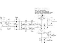
You can use this part from Digikey: 296-21624-5-ND . It's a Texas Instruments 7815 and good for 1.5 Amps of current and it has a power supply rejection ratio of 78db which is pretty good for these kind of regulators. You should also get some solder wick from Digikey while you are at it since it makes de-soldering easy.This is a follow up post to my previous posts on a whammy PSU that is not performing as expected. I have made some changes. I removed the LED's after figuring out that that I had installed D5 backwards. Unfortunately they did not come easily and are now unusable. Given that I installed jumpers accross R9 and R23 to use the "naked regulator" option. I checked the ground pin on the 7815 reg and got a solid ground. When I checked with my voltmeter between the input and output leg I discovered a short. Does anyone have a suggestion for replacements of the voltage regulators? Or at least 7815? I did a brief search on Digi-key but I'm not sure what to look for in terms of output current and other parameters. Thanks everyone!
There was a bill of materials for this at the beginning of the thread. Test for shorts after you have soldered the parts in and look closely for solder bridges from excess solder between pins. Get a few extra LEDs. Look at the LEDs closely before you put them in. There is a flat surface on the case of the LED near the pin that is cathode lead (the line part of the schematic symbol). The longer of the two leads is the anode (the triangle part of the schematic symbol). Be certain that your LED is oriented correctly before you solder. Enjoy!
Hey YouAgain,
Thanks for your response. The information will be helpful I'm sure. I will make those checks you suggested after I have everything soldered. Have a good day.
Thanks for your response. The information will be helpful I'm sure. I will make those checks you suggested after I have everything soldered. Have a good day.
When I checked with my voltmeter between the input and output leg I discovered a short.
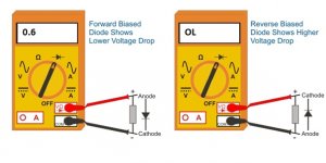
I know a 'short is a short' 🙂 but are you reading this on a 'low ohms' range capable of resolving low ohm values? Also are you sure the diode across the reg is OK?
If your meter has a diode setting try using that. Measure (in both directions) with the diode setting and see it you get something in the 0.6V to 0.7V range.
https://electronicspost.com/how-to-test-a-diode-with-a-multimeter/
https://electronicspost.com/how-to-test-a-diode-with-a-multimeter/
Attachments
Hey everyone,
This is a follow up post to my previous submissions regarding my Whammy headphone amp with malfunctioning PSU. Originally I had an unlit D5 LED and a reading of 30 volts on the positive rail.
After reading through the reply from other members, I decided to replace both LED's as well as regulator 7815. I also removed the temporary jumpers on R9 and R13that I installed prior to receiving my new parts. I broke what I consider a cardinal rule of repair which is, don't start replacing parts until you know for sure what the problem is. However, sometimes you get lucky. I now have two functioning LED's and 16.8v on the positive rail and -16.3 on the negative.
Thank you to everyone who responded to my posts. I also added a digital multimeter,, a desoldering pump and a component multitester to my toolkit. Now...onward with the build!
P.S. In hindsight, I believe the problem was a defective LED at D5.

I get noticeable hiss when the amp is on and volume at zero with my AKG K371s.
With AKG K712s the Whammy is silent. I don't hear any hiss.
Has anyone experienced this with K371s?
With AKG K712s the Whammy is silent. I don't hear any hiss.
Has anyone experienced this with K371s?
The sensitivity of the 712 is (very) significantly lower than the 371 at 105dv/V vs 114db/V (figures from AKG spec sheets). The 371 is also approx half the impedance.
So I would say what you hear is to be expected tbh.
So I would say what you hear is to be expected tbh.
Simple answer would be yes (alter the feedback ratio by lowering R4 and R8) but whether it would need any tweaks of the caps across those resistors for stability and response might need to be researched. Try it first of all and see if it helps. Try a 1k.
I changed R4 and R8 to 1k and the hiss is gone. The op-amp I'm using is Muses 8920 and I don't use caps on C2 and C7.Simple answer would be yes (alter the feedback ratio by lowering R4 and R8) but whether it would need any tweaks of the caps across those resistors for stability and response might need to be researched. Try it first of all and see if it helps. Try a 1k.
I have a suitable switch on my parts box and I'll build a gain switch with 1k and 4.75k resistors.
Thanks!
That's good 👍.
The switch should be make before break. If it is not then the circuit will operate with no feedback for a fraction of a second and that will probably cause a massive click in the headphones as DC offset appears. Also if any signal is present then the circuit will be operating at truly massive gain. So make before break... or have the switch shunt the 1k across the 4.75k. That should be essentially silent.
The gain would be fractionally lower still that way so you could use a 1k2 instead. Experiment 🙂
There's still plenty of gain for K712s with 1k so I think I'll leave it as is. Using 50k Alps pot.
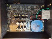
This is a follow up to my previous posts regarding my Whammy project with the malfunctioning power supply. My project is now finished and works like a charm. Worked from first power-up. No smoke or other issues.
The amp is dead quiet. I'm amazed at the details I can hear even through modest Audio-technica ATH-M30 phones. Steely Dan never sounded so good.
Thank you to Mooly and everyone else that offered tips and suggestions during the build. Also Thanks to Wayne C, Nelson P, and the diy team for making quality equipment like this available to the rest of us. Of course I now have a dilemma. What to build next!
Dave Munson
- Home
- Amplifiers
- Pass Labs
- "WHAMMY" Pass DIY headphone amp guide