Sonic Imagery opined that the “upgraded “ version would not make a noticeable difference in the Whammy circuit. As I am always “in for a penny, in for a pound “ I was prepared to shell out a little more.I've been using the Sonic Imagery Labs dual discrete for most of the year and they are excellent. I have no desire to try any other op amps in my Whammy now but it would be nice to have a Whammy board layout that would allow using single channel discrete Op Amps in the standard API footprint because I have lots of different flavors of them used with pro audio gear that I would love to try in the Whammy.
Sonic Imagery Labs sells direct and if I remember right they offer these with a parts upgrade that gets you tantalum chip resistors and maybe something else. It's not obvious on the web site when ordering so if that interests you hunt around for it. I may have chosen that but I didn't notice it until after I'd ordered and they don't make mention of the upgrade price.
If you like high quality parts for the Whammy try out Belleson SPX voltage regulators. I've been using the 24 Volt version with the Sonic Imagery Labs dual discrete so I have lots of headroom to drive most anything as a preamp. Belleson has an real interesting web site which shows direct comparisons with all kinds of other voltage regulators including the Jung Super regulator, Shunt types and many others. It is impressive. He sells direct but you may find a better price at Parts Connexion if they are in stock.
I couldn't be happier with my Whammy. I used the Quasimoto style snubbers on the power transformer. I squeezed in four film capacitors to jumper the 22 uF electrolytics downstream of the op amps and I put in a pair of two pin headers that let me jumper across the input film capacitor pair since most of my sources have no DC so they aren't needed but capacitors are there if I do need them.
It's been fun but the best part is enjoying the music. The hardest part was getting the film caps to fit with the electrolytics.
Yes he mentioned about a 2 db improvement in the noise floor and the resistors are Vishay foils not tantalums. Best for the input to an AD converter perhaps.


Wow..the Whammy license plate! The next thing you know the Whammy may be on the menu at the US Denny's diner restaurants. Right between "Slams" and the "Moons Over My Hammy".
A Ham Whammy sounds appetizing to me early in the morning. It might even get the amature radio guys excited.
A Ham Whammy sounds appetizing to me early in the morning. It might even get the amature radio guys excited.
Hey Everyone,
This is my first post. I am a newcomer to the community, let me know if I am posting incorrectly.
I need some feedback from someone with more experience regarding my project. I am constructing my recently purchased Whammy headphone amp.
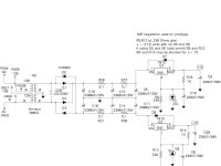
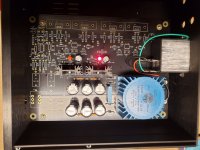
The problem comes to light when I power on the PSU and check for proper voltage. The negative side reads -18.1 volts which I understand is great. The positive side however, shows 30 volts. Additionally, one of the LED's fails to light. I suspect the nonlit LED is on the affected circuit. Any suggestion what I might check before disassembling the affected side and replacing components? I have attached the schematic and a photo of the board under power. Thank you in advance for any suggestions.
This is my first post. I am a newcomer to the community, let me know if I am posting incorrectly.
I need some feedback from someone with more experience regarding my project. I am constructing my recently purchased Whammy headphone amp.
The problem comes to light when I power on the PSU and check for proper voltage. The negative side reads -18.1 volts which I understand is great. The positive side however, shows 30 volts. Additionally, one of the LED's fails to light. I suspect the nonlit LED is on the affected circuit. Any suggestion what I might check before disassembling the affected side and replacing components? I have attached the schematic and a photo of the board under power. Thank you in advance for any suggestions.
Attachments
Welcome to diyAudio 🙂This is my first post. I am a newcomer to the community, let me know if I am posting incorrectly.
Quick things to check...
1/ That the 7815 really is a 7815. Look very closely at the markings. Make sure.
2/ That D7 is correctly fitted.
3/ That you have no shorts between any pins of the 7815
Things to measure.
With it on measure the voltage across R9. What do you see?
With it switched OFF check you have no short across D7.
Thanks for responding Mooly. I will check those issues out. It's going to take me some time as I am away from the workbench right now. But I definitely will try those checks and post the results when able. Thanks for your time.
OK 🙂 and good luck. Whatever is going on is probably something simple. There are very few possibilities really.
Hi UncleMudHey Everyone,
This is my first post. I am a newcomer to the community, let me know if I am posting incorrectly.
I need some feedback from someone with more experience regarding my project. I am constructing my recently purchased Whammy headphone amp.
The problem comes to light when I power on the PSU and check for proper voltage. The negative side reads -18.1 volts which I understand is great. The positive side however, shows 30 volts. Additionally, one of the LED's fails to light. I suspect the nonlit LED is on the affected circuit. Any suggestion what I might check before disassembling the affected side and replacing components? I have attached the schematic and a photo of the board under power. Thank you in advance for any suggestions.
Interestingly, I had the exact same issue but with the opposite rail. The correct value on positive, but -30 volts or so.
I get the right voltage across C6 and C11. I replaced the 7915, diode, and LED to no effect.
I ended up abandoning that PCB and bought a new one from the store, and full replacement parts for the PSU. worked perfectly after that using the rest of the existing kit.
I do want to get back to solving it, as a personal challenge, but haven't had time. Hopefully the solution that solves yours, solves mine, too.
Hey Craig,
Thanks for the information. I will keep this in mind as I explore the issue. I appreciate your time.
Thanks for the information. I will keep this in mind as I explore the issue. I appreciate your time.
Just something to check... Look closely at the board traces (maybe with magnification?) for any unetched copper between traces that shouldn't be there. If it's coated it will be even harder to spot. If you don't find anything visually you should pull the parts off (carefully!) and check between traces with a meter. Also check that via's connect top and bottom of pads. I always solder both sides (where possible) to eliminate the possibility.
It's rare but can happen. I got one board a while back (out of many purchased, not Whammy) that had a tiny bridge of copper between 2 traces that wasn't completely etched away. Drove me nuts until I finally spotted it. It was green coated. Black is worse. Good luck!
It's rare but can happen. I got one board a while back (out of many purchased, not Whammy) that had a tiny bridge of copper between 2 traces that wasn't completely etched away. Drove me nuts until I finally spotted it. It was green coated. Black is worse. Good luck!
This is a follow up to my previous posts. Regarding my Whammy kit with 30 volts on the positive rail. I checked the voltage regulator and it is indeed a 7815. Also, I found no unsoldered pins, nor did I find any solder bridges between pins.
In the interest of time, I have decided to order a new PCB and populate it with new power resistors, capacitors and diodes. I will also replace the voltage regulators. I will disassemble the original board at a later date and test each component to try and determine what is wrong. If I come up with anything I will post it for the benefit of anyone who runs into the same problem. Thanks again to everyone who responded to my post.
In the interest of time, I have decided to order a new PCB and populate it with new power resistors, capacitors and diodes. I will also replace the voltage regulators. I will disassemble the original board at a later date and test each component to try and determine what is wrong. If I come up with anything I will post it for the benefit of anyone who runs into the same problem. Thanks again to everyone who responded to my post.
Hi Dennis,
Thanks for your reply. Because it's an easy task, I think I will rotate it and reinstall. The PSU isn't usable the way it is, so I'm not out anything to try that. Thanks for the suggestion.
Thanks for your reply. Because it's an easy task, I think I will rotate it and reinstall. The PSU isn't usable the way it is, so I'm not out anything to try that. Thanks for the suggestion.
This has to be something simple. The regulator output is +15 volts added to whatever voltage the middle pin is at. Just connect the middle pin of the reg to ground and see if you get +15 volts.This is a follow up to my previous posts. Regarding my Whammy kit with 30 volts on the positive rail. I checked the voltage regulator and it is indeed a 7815. Also, I found no unsoldered pins, nor did I find any solder bridges between pins.
If you still see 30 volts at the output then either the reg is faulty, the ground around the reg is not ground (broken print... actually check that the middle pin has continuity to the print and make sure the pad is not broken or lifted such that it is isolating that pad from the print). The only other possibility is a 'short' from the input side of the reg to the output.
Check that pad first though.
Hey Mooly,
Thanks again for the input. I am a beginner so I am not as fluent in the function of each component as some. I will explore these suggestions, hopefully this afternoon. The more I interact with other members, the more I learn. I can see how your suggestions make sense given the limited number of connections at this point in the process.
Thanks again for the input. I am a beginner so I am not as fluent in the function of each component as some. I will explore these suggestions, hopefully this afternoon. The more I interact with other members, the more I learn. I can see how your suggestions make sense given the limited number of connections at this point in the process.
As far as source goes when using a HP amp, can I just plug in my turntable RCA's and listen? Circumstances may somewhat force me into a position where the best sound quality comes from headphones.
What to do with all of our stereo amps? Mothball them I suppose.
What to do with all of our stereo amps? Mothball them I suppose.
Usually you need a phono preamp to boost and eq the signal properly. The level out of turntables is too low and riaa eq hasn't been applied, unless the turntable has a built in preamp.As far as source goes when using a HP amp, can I just plug in my turntable RCA's and listen? Circumstances may somewhat force me into a position where the best sound quality comes from headphones.
What to do with all of our stereo amps? Mothball them I suppose.
- Home
- Amplifiers
- Pass Labs
- "WHAMMY" Pass DIY headphone amp guide