Please ground the regulator center pins, as Mooly advised, then measure regulator VIN or volts to ground at R37 and R38.Hi,
I need your help, please!
Completed the Whammy kit but no sound. The light bulb tester switches on since at pcb AC input I measure 175 VAC instead of 230 VAC (I am in Europe). The red led (standard regulation) switches on, but at C9 pads 4.75 VDC instead of 15, whereas between R13 and R14 I measure 0VDC instead of 15.
The PSU test was ok before completing population of the rest of pcb. I replaced the op-amp without success and removed wiring to ground, input and output jacks, again no solution.
I also double checked resistors and caps.
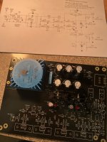
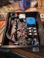
I attach a couple of pictures of current populated pcb.
No idea on what to try next. Please help me or address me where I can find a diagnosis roadmap
Renato
VIN should be +- 20vdc or more. If a VOUT is less than 15vdc, then the regulator max ampere is exceeding and the regulator is protecting itself.
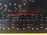
Measure across R16,R22,R29 and R32 is 3.19VDC. I connected C13 and C23 as in the attached picture, I tested again and the measure is 3.17VDC. at all 4 resistors!You need to take measurements to see where the current is flowing.
Try measuring the DC voltage across all four of the 10 ohm resistors (R16, R22, R29 and R32) that connect to the output FET's. There should be around 0.6 volts across each.
If the voltage across both the resistors is high then switch off and place a wire link across C13 and C23 and retest.
If the voltage across only one of the resistors in each channel is high then check for a short to ground at the output (the junction of the 10 ohm resistors)
Renato
Attachments
Vin between R37 and U3 ground (center pin): +2.92VDC.Please ground the regulator center pins, as Mooly advised, then measure regulator VIN or volts to ground at R37 and R38.
VIN should be +- 20vdc or more. If a VOUT is less than 15vdc, then the regulator max ampere is exceeding and the regulator is protecting itself.
Vin between R38 and U2 ground (center pin): 1.18mVDC.
Vout between R10 and U3 ground: -4.3VDC.
Vout between R14 and U2 ground: +7.18VDC.
Here in Italy is after midnight: it is time to sleep ....
Renato
Non of those measurements makes any sense. You should start by checking your multimeter battery. Multimeters tend to make nonsense if the battery is flat.
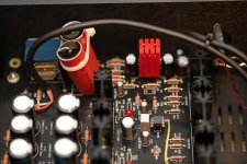
Do you have any thermal pads between the regulators, outputs mosfets and the heat sinks? Like mica pads & thermal paste or silicone pads? I do see insulators on the screws but I don't see any thermal pads. That would cause a short if the heatsinks are grounded.
Try measuring the DC voltage across all four of the 10 ohm resistors
Measure across R16,R22,R29 and R32 is 3.19VDC. I connected C13 and C23 as in the attached picture, I tested again and the measure is 3.17VDC. at all 4 resistors!
And you are measuring across these ? The voltage across each.
Look at the circuit. If you have 3 volts across these then that means you have I=V/R which is 3/10 = 0.3 amps flowing. That would load and kill the power power supply rails.
Adding a link across C23 should remove any forward bais voltage to the FET's and force a zero bias current.
So something is wrong. Either the 3 volts you measured is not across the resistors 🙂 or the reading is real and the FET's have a problem.
Following the guide on this website, it is not necessary to put insulator pads because the heatsinks are not grounded. I just used some thermal grease as suggested.Do you have any thermal pads between the regulators, outputs mosfets and the heat sinks? Like mica pads & thermal paste or silicone pads? I do see insulators on the screws but I don't see any thermal pads. That would cause a short if the heatsinks are grounded.

I am going to repeat all measurements you and fubar3 suggested double checking with two different multimeters🙂And you are measuring across these ? The voltage across each.
Look at the circuit. If you have 3 volts across these then that means you have I=V/R which is 3/10 = 0.3 amps flowing. That would load and kill the power power supply rails.
Adding a link across C23 should remove any forward bais voltage to the FET's and force a zero bias current.
So something is wrong. Either the 3 volts you measured is not across the resistors 🙂 or the reading is real and the FET's have a problem.
renato
I just double checked with two multimeters and I confirm that that at both pins of R16, R22, R29, R32 I measure about 3VDC.
Things are even getting worse because yesterday both D5 and D6 leds were lighting but now D5 is off.
Can I continue to make measurements?
As you see I am not expert; I can follow instructions without understanding too much. I was able to easily build a couple of gainclones, the B1 Korg, the Aleph J amp and even a DAC with smd but now I realize I was just lucky
Renato
I just double checked with two multimeters and I confirm that that at both pins of R16, R22, R29, R32 I measure about 3VDC.
For reference... lets just be clear on this because it is so important. To measure you place one meter lead on one end of the resistor and the other meter lead on the other end of the resistor. The voltage you see is then the voltage across the resistor which then allows us to calculate the current flow.
If you have 3 volts across the resistors then the output stage is drawing excess current.
If you were measuring from ground to the resistors then you have a DC offset issue and the current in the resistors is still an unknown.
I found an error! I inverted the position of Q3 and Q4.
And... does it work now 🙂
So: the VDC measures were correct: 3VDC.For reference... lets just be clear on this because it is so important. To measure you place one meter lead on one end of the resistor and the other meter lead on the other end of the resistor. The voltage you see is then the voltage across the resistor which then allows us to calculate the current flow.
If you have 3 volts across the resistors then the output stage is drawing excess current.
If you were measuring from ground to the resistors then you have a DC offset issue and the current in the resistors is still an unknown.
And... does it work now 🙂
It is the first time for me to remove a three pin device, hard job. I'll let you know the advances, but not so quickly, I started this project 5 months ago and still....
Renato
No 🙂So: the VDC measures were correct: 3VDC.
Like this. The voltage ACROSS any of the 10 ohm resistors should be about 0.6 volts.
The voltage from ground to the resistor centre point (the output) should zero.
The MOSFETs are easily damaged when removed from the foil wrapper. I don't use a static strap but I work on a metal tray to minimize static.It is the first time for me to remove a three pin device, hard job. I'll let you know the advances, but not so quickly, I started this project 5 months ago and still....
Bad or incorrect components are best removed with an extraction workstation. It only applies heat for perhaps 2 seconds and does not spray solder particles like those economy sucker tools. Lacking that, it is best to cut the component wires or pins before unsoldering the pads.
Forgive me for my poor English: are you suggesting me to replace current fets with new ones instead of trying to re-use them?The MOSFETs are easily damaged when removed from the foil wrapper. I don't use a static strap but I work on a metal tray to minimize static.
Bad or incorrect components are best removed with an extraction workstation. It only applies heat for perhaps 2 seconds and does not spray solder particles like those economy sucker tools. Lacking that, it is best to cut the component wires or pins before unsoldering the pads.
Renato
I find it difficult to replace these 3pin devices under heatsinks so I cut the pins and pluck them one at a time with tweezers. However, if I did not have a spare handy, I might try to reuse a device rather than order another...are you suggesting me to replace current fets with new ones instead of trying to re-use them?
Perhaps someone can suggest a test circuit for your FETs, I don't have one.

I am pleased to submit my first post after trolling for months. My first build is complete and was an overwhelming success. Following step by step with testing along the way, this build was 100% right out of the gate. Thank you Wayne, and thank you Nelson for allowing this astounding support to the DIY (poor) community.
Attachments
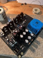
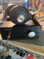
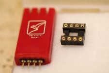
FWIW, I used R9/R10 for Power LED with 10K resistor and 100K on the Pre-outs - not clear in photos. Have not used as Pre yet, but will follow up when I do. Thanks to all who contributed to this thread that gave me the confidence to dive into this project. My last ‘real’ HP amp was a Focal Arche. From an amp perspective, this build is all of what the Arche was after the Burson opamp upgrade.I am pleased to submit my first post after trolling for months. My first build is complete and was an overwhelming success. Following step by step with testing along the way, this build was 100% right out of the gate. Thank you Wayne, and thank you Nelson for allowing this astounding support to the DIY (poor) community.
- Home
- Amplifiers
- Pass Labs
- "WHAMMY" Pass DIY headphone amp guide