I've been playing my WHAMMY for two years now and I have just read that C26, C27, C2 & C7 are actually optional.
I have now removed C2 and C7. C26 & C27 are still in.
Not sure what to do with C26 & C27 now... I use it with RC4580, OPA1642 (not bipolar) and it plays nicely. I also want to try bipolar OPA1612.
Do these capacitors (C26, C27) have any impact on sound quality? In long term, do I have to remove them if I decide not to use bipolar at all or can they stay anyway (also when using non-bipolar opamps)? 😉
I can't seem to get my OPA1612aid to work. Wonder if i can get any help? My Whammy works well with RC4580, AD823anz, opa2132. I do not have the compensation caps C2,C7 installed. and these are the adapters I use for opa1612aid
https://my.element14.com/aries/lcqt-soic8-8/ic-adaptor-8-soic-to-dip-2-54mm/dp/2476033
I made sure the soldering of all joints is done under 1-2 seconds, and I even used a multimeter to test for continuity to ensure the joints are correct with the opamp in whammy. I'm pretty sure solder joints/soic pin to dip 8 pin matches.
When i turn it on, left channel have DC offset that's fluctuating around 30-50mV. it can rise as high as 200mV. and right channel have DC offset of 8V. I only measured this after plugging my headphones in. I was very lucky i did not bust my headphones. But when I had my headphones on, it has this pink noise. and intermittent pink noise. and only the left channel works. I think probably the dc offset on the right channel is way too strong. I'm not sure if I have received a faulty unit. I bought this from farnell. Is there any way to test it?
Thanks!
Last edited:
Assuming the 1612 is installed properly and it wasn’t damaged attacking it to the adaptor, if you replace the opamp with a different one, and the whammy works properly, then it’s a pretty good chance that it’s faulty.
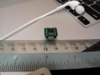
I'm not that impressed with the adapter you are using. Pin 1 is not marked on either the SOIC pads or the DIP pinout. I'm not sure why the PCB maker left the vias unmasked. It's asking for trouble with potential solder bridges between them.
Have you soldered the 8 big square pins to a spare socket to allow plugging into the board socket?
Have you soldered the 8 big square pins to a spare socket to allow plugging into the board socket?
Attachments
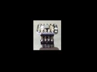
Here are some photos of it.
No I did not solder it to a spare socket, instead I just plugged it in straight any reason for soldering into a spare socket? I'm using the sparkfun one that was posted somewhere in this forum and that is very tight.. Note I did sand down the pcb smaller to make insertion possible.
I forgot to check for solder bridges which I will promptly do so now.
Unfortunately I was impatient for waiting for my soic8-dip8 adapter from ebay as it has been 2 months. So this adapter in picture was the only one I could get within a week's time from Farnell.
Attachments


Terence can you show the type of PCB socket you have pal? Ideally the pins should match perfectly - it looks like you might be putting a square peg into a round hole 😉
If the board socket is one of those nice mill max round pin jobs, then it might be best to permanently solder the new square adapter pins into to a similar mil max adapter.
I had to do it with the OPA1622 from ebay like below.
Is the OP-amp pin 1 the opposite end of the 'ARIES' logo?
If the board socket is one of those nice mill max round pin jobs, then it might be best to permanently solder the new square adapter pins into to a similar mil max adapter.
I had to do it with the OPA1622 from ebay like below.
Is the OP-amp pin 1 the opposite end of the 'ARIES' logo?
Attachments


Last edited:
Hey Rich
This is the PCB socket i used
PRT-07937 SparkFun | Mouser Malaysia
and yes the Op-amp pin1 is the opposite end of the Aries logo. Sorry if the picture isn't very clear, but there is a small dot there that indicates it's pin 1.
Terence
This is the PCB socket i used
PRT-07937 SparkFun | Mouser Malaysia
and yes the Op-amp pin1 is the opposite end of the Aries logo. Sorry if the picture isn't very clear, but there is a small dot there that indicates it's pin 1.
Terence
Attachments

Ah, I think those type are more intended for the standard large DIP8 package with flat pins. But, I imagine you should get contact with your new adapter, you say it pushes in a bit but it's very tight?
You got the op-amp installed fine then. And you have done continuity test. It's a dud!
No harm in contacting Farnell for replacement if you got them from there. It's certainly one way to find out.
You got the op-amp installed fine then. And you have done continuity test. It's a dud!
No harm in contacting Farnell for replacement if you got them from there. It's certainly one way to find out.
Yeah. Seems very likely to be a dud. I tried contacting them but I'm required to give a lot of explanation and measurements of which some are beyond me and I don't think a DMM alone will be able to measure them.
So I guess I'll order and try a new one and see how it goes.
So I guess I'll order and try a new one and see how it goes.
Attachments

Actually Terence, no DMM is required maybe. For each question try this -
1) Give them a pic of their packaging with label showing order number so that they know you aint cheating 😉
2) Yes, unit failed to operate first time despite good continuity between contacts. The unit was mounted on (their adapter part #)
3)Unit failed to operate, no physical defects were found prior to assembly.
4)The load is restive, not sure of the operating current as the unit failed to work.
4)Dry atmosphere, 25C
5)Unit was installed on mounting adapter (part #) and inserted into a PCB socket. The socket and amplifier audio circuit is fully functional with no defects having previously been tested with multiple op-amps (list op-amps if you like) DC voltage to the unit is (state voltage) provided by a fully regulated linear supply. ( send pics of unit and adapter)
Hopefully that might work, they just want to know you are no cheating fool and understand how to use the item. Give it a go pal. A few good pics will help.
If they refuse then resort to threats and violence. Dedicate your life to exposing their fraudulent behaviour...
If you don't get what you want, smash the place up. General policy in life.
😉
If you don't get what you want, smash the place up. General policy in life.
😉
While you are making an order, I suggest you also purchase a different opamp in DIP-8, as reference, and in order to verify that everything else works well. For example. LM833. It's inexpensive, sounds fantastic in this circuit, and is common.
6L6:
You missed terenceng's earlier post #2422 where he says: "My Whammy works well with RC4580, AD823anz, opa2132...."
You missed terenceng's earlier post #2422 where he says: "My Whammy works well with RC4580, AD823anz, opa2132...."
Hello Folks,
Im trying to decide if to do this build but I don't have the experience.
I built the Pearl 2 with a lot of help from Jim (thanks again Jim).
Can you guys comment on the sound quality of the amp? What is it comparable to?
What do you guys recommend?
Thank you.
-Cheers,
Fabricio
I did this build without experience. I didn't even know how to read a schematic. As long as you can solder it's very easy. Tons of help here and the amp is awesome. I found the stock RC4580 op amp to be (to put it mildly) crappy. But everyone has their own preference. For me by far the best op amp that I've used is the OPA2134PA which at $4.79 happens to be the cheapest of the 4 I tried (not including the RC4580). I would recommend a non anodized/painted case - that way you don't have to spend time sanding surface areas to ensure ground continuity.
Last edited:
- Home
- Amplifiers
- Pass Labs
- "WHAMMY" Pass DIY headphone amp guide