Mark, why didn't you tap from one of the rectifier diodes on the board instead?Anything bad if we do this? Also what value is the resistor?
The capacitors are what cause the slow fade.
The rectifier diode is a 1N3595 because I've got a drawer full of them; they are small and have very low reverse leakage current, so the LED is very well protected. Probably a 1N4148 would have worked well enough. The LED is a wide viewing angle (112 deg) blue diode whose brightness rating is pretty high: 5000 mcd. So I'm running it at about 1 milliamp of RMS current.
I decided to do my LED brightness experiments on the lab bench rather than within the guts of an AC mains powered piece of audio gear. Just a preference of mine.
My step by step experimental procedure was roughly this
- Choose an LED from among the ones in my parts drawer. I happened to pick a part with an extremely wide viewing angle AND a fairly high brightness. Others will doubtless make different choices.
- Connect this LED to a potentiometer, DC power supply, and DVM in DC current ("ammeter") mode.
- Fiddle with the power supply and/or with the potentiometer, applying different amounts of current as measured on the ammeter, until I find a setting which gives the LED brightness I like best. Write down the current. (Notice it is DC current because the power supply is also DC).
- Figure out the necessary resistor value to give that amount of current (remember: now it is RMS current!) when the LED and the 1N3595 are connected to the AC waveform from the transformer secondary
- Solder together the 1N3595, LED, resistor assembly and cover everything with heatshrink tubing for safety
- Connect to the transformer secondary and verify (i) it works correctly; (ii) it gives the desired brightness
Of course, there are plenty of other ways to skin the cat. One that uses no lab equipment whatsoever, is this: Connect the 1N3595 (or 1N4148) in series with your LED, and connect a 50K potentiometer in series with that. Attach the whole assembly to the secondary of your piece of audio gear. Dial the potentiometer until you get the LED brightness that you like best. Stop, turn off the gear, remove the potentiometer, and measure its resistance. Shazam! That's the fixed resistor value you want.
It requires no DVM, no DC power supply, and no RMS computations. But it does require you to manipulate circuitry which is connected to live audio gear powered from the potentially lethal AC mains.
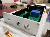
A few people have asked for Cap MX boards so I thought I would post some pics and advice regarding installation.
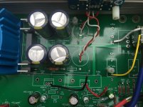
Before you populate the large components, remove Whammy last filter caps and resistors, solder 5.1R's back under the whammy board. Then place your CapMX board in position and mark holes in appropriate location. In the first pic you will see only two holes are required for pillars, one in each corner.
Only three wires are really needed to the capMX, pos/neg and ground.
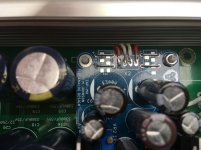
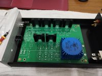
Please note in second pic that the rectifiers have to be linked out with four resistor wires as shown, then run the DC output straight to the CapMX.
If you wanted to wire the LED's to the front panel, that is fine. They are for indication and not part of the business end.
The only critical caps are the C4/C8 1000Uf multiplier caps (will be included with boards), for the rest use what you have that will fit with correct 25V - 35V rating. Some of you are using 22V transformers will give around 30VDC into the MX board so some heatsinks on the BJT's are required maybe.
BJT's can be anything with correct pinout - TIP41/42 or BD139/140 for instance.
Hope that helps 😉
Before you populate the large components, remove Whammy last filter caps and resistors, solder 5.1R's back under the whammy board. Then place your CapMX board in position and mark holes in appropriate location. In the first pic you will see only two holes are required for pillars, one in each corner.
Only three wires are really needed to the capMX, pos/neg and ground.
Please note in second pic that the rectifiers have to be linked out with four resistor wires as shown, then run the DC output straight to the CapMX.
If you wanted to wire the LED's to the front panel, that is fine. They are for indication and not part of the business end.
The only critical caps are the C4/C8 1000Uf multiplier caps (will be included with boards), for the rest use what you have that will fit with correct 25V - 35V rating. Some of you are using 22V transformers will give around 30VDC into the MX board so some heatsinks on the BJT's are required maybe.
BJT's can be anything with correct pinout - TIP41/42 or BD139/140 for instance.
Hope that helps 😉
Attachments
Last edited:
Yes I'd say so Thomas, you could run the CapMX and the standard regs from the CRC supply, the regs could power the back end while the MX board powers the op-amp for instance.
Fantastic. Sounds like a plan for next weekend. 🙂
PM sent.
Thank you.
Edit - all the current batch of Cap MX boards have been taken, I will certainly order more kits soon.
Would installing an XLR output instead of TRS jack be possible on the Whammy with its current configuration?
Would installing an XLR output instead of TRS jack be possible on the Whammy with its current configuration?
Heh! Literally came in to ask this same question. Tried to search the thread only to find somehow 0 mentions of XLR in any sense.
You can use whatever connectors / pinouts you choose. It may be relevant to ask why you'd like to use XLR in this case.
Hello Folks,
Im trying to decide if to do this build but I don't have the experience.
I built the Pearl 2 with a lot of help from Jim (thanks again Jim).
Can you guys comment on the sound quality of the amp? What is it comparable to?
What do you guys recommend?
Thank you.
-Cheers,
Fabricio
Im trying to decide if to do this build but I don't have the experience.
I built the Pearl 2 with a lot of help from Jim (thanks again Jim).
Can you guys comment on the sound quality of the amp? What is it comparable to?
What do you guys recommend?
Thank you.
-Cheers,
Fabricio
Just connect both L-/R- (pins 2 and 4) on the 4 pin XLR socket to output ground.

Out of curiosity, usually the 'ground' is actually an inverted signal. Would that ever be a problem? I assume not if this is being used as a headphone amp, but unsure if it is being used as a preamp.
For preamp out you can, (I'll need someone to correct me if I'm wrong, this is what I did with a previous headphone amp) short the -ve output to the ground. That's also what RCA to XLR cables do.
I can understand where some people would need this connection. Sometimes you only have balanced equipment downstream.
I can understand where some people would need this connection. Sometimes you only have balanced equipment downstream.
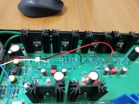
Offsets with the stock opamp is roughly ~4-5mV on both channels, matched perfectly too. Decided to swap it out with the Burson V5, went down to ~0.1-0.3mV on both channels.
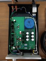
Running on 18V transformers with 10 ohm resistors the bias is 56.2mA. Heatsinks running at cool 43 celcius (109.4 fahrenheit).
Everything sounds correct. What a fun build.
Running on 18V transformers with 10 ohm resistors the bias is 56.2mA. Heatsinks running at cool 43 celcius (109.4 fahrenheit).
Everything sounds correct. What a fun build.
Attachments
-
 IMG_20200510_200026.jpg793.5 KB · Views: 236
 -
 IMG_20200510_200007.jpg444.3 KB · Views: 223
 -
 IMG_20200510_195949.jpg373.8 KB · Views: 246
 -
 IMG_20200510_195940.jpg612.8 KB · Views: 264
 -
 IMG_20200510_195053.jpg433.5 KB · Views: 523
 -
 IMG_20200509_135243.jpg583.7 KB · Views: 526
 -
 IMG_20200507_224620.jpg706.9 KB · Views: 528
 -
 IMG_20200507_223654.jpg910.7 KB · Views: 621
Last edited:

Hi fabriciom,
This was my first DIY build ever, and I think that it's one of the best project to start with:
- Great guide to guide you step by step
- Lots of active poeple in this thread to help you in cas needed.
- The board is of great quality and has enought space for easy soldering.
As for the sound quality, it seems to be excellent, performing at the level of much more expensive amplifiers according to the various feedback I ve seen online.
On my side I compared it to the JDS Atom (100$); and it is clearly superior in all aspects.
Also, it's fun (and extremely versatile) to be able to change the character of the amp by swapping Op Amps, for better synergy with your source / headphones.
On my side I compared it to the JDS Atom (100$); and it is clearly superior in all aspects.
Also, it's fun (and extremely versatile) to be able to change the character of the amp by swapping Op Amps, for better synergy with your source / headphones.
I think this might have just put me over the line in deciding to order the kit.
For years I have used a JDS Labs ODAC+O2 combo. Just finished an OTL tube amp build and am on the lookout for another fun project, a quality SS headphone amp might be it I think.
I feel like if I'm going to build an SS headphone amp it might as well be good and was just looking for info on how it sounded compared to other products on the market.
Hello Folks,
Im trying to decide if to do this build but I don't have the experience.
I built the Pearl 2 with a lot of help from Jim (thanks again Jim).
Can you guys comment on the sound quality of the amp? What is it comparable to?
What do you guys recommend?
Thank you.
-Cheers,
Fabricio
Fabricio, I can tell you that if you install all components correctly this amp will work first time. For the Money and sound quality this is one of the best little headamp projects out there. Forget Shiit and O2, I've heard them.
Remember, this is basically a simplified version of the mighty Pass Labs HPA-1, using op-amp front end instead of discreet parts with hard to find matched JFets. With the right op-amp that suits you and a decent potentiometer this amp is excellent and can handle a bit of tinkering 😉
Build to the standard BOM first time and you will be happy I assure you.
Choosing op-amps is almost the hardest part but the OPA's from TI (Burr Brown) are all generally very good place to start, try OPA1642 or even OPA1622 from ebay. The OPA1656 also looks like it will be very good.
I like the LT1128's right now, very decent sound, but the OPA627BM's really take the prize so far. I have a discrete dual op-amp coming from Sonic Labs so will see how much better than the 627's they are.
Just connect both L-/R- (pins 2 and 4) on the 4 pin XLR socket to output ground.
Just to be clear, am I inserting two ground wires into the hole of the PC board where it says ground and then inserting one of each wire in pins 2 and 4? Can you please explain this a bit more? I want to make sure I get it properly installed.
If you're planning to use headphones with a 4 pin XLR, yes that's the way.
Much appreciated good sir!
- Home
- Amplifiers
- Pass Labs
- "WHAMMY" Pass DIY headphone amp guide