I'm running the double WHAMMY boards as a pre-amp for Purifi class-D power amps. As these power modules like a good drive I'm using the circuits as is and did not include any more series output resistance than the already existing 10ohm resistors in MOSFET stage.
I have also short circuited both C1/C5 and C26/C27... as no capacitor is better than arguing which capacitor sounds better. DC offset at power amp output is < 8mV, which I deem perfectly fine and safe.
Switching the output via a 6.5mm plug contacts should also be just fine.
I have also short circuited both C1/C5 and C26/C27... as no capacitor is better than arguing which capacitor sounds better. DC offset at power amp output is < 8mV, which I deem perfectly fine and safe.
Switching the output via a 6.5mm plug contacts should also be just fine.
Attachments
I wanted to follow up on this in case anyone else was interested in trying the Sparkos regulators. They are indeed drop-in replacements and handle the same specs as the 7815/19s that are used in the 'stock' Whammy PS (+/- 15VDC @ 1.5amps max). I ordered some and will use them in my second Whammy build. I'll report back on the impact after I've had some time to listen/measure things.
I took a look at the Sparkos regulators last night based on the thread here and have a simple question as it is not obvious from their data sheet: are these drop in replacements for the 7815/19s (i.e.: pin for pin and resistor/bypass caps) ? The data sheet discusses recommendations for certain types of caps to be attached close to the regulators.
The other question is: is it worth the hassle/cost? I can say for sure that their dual-discrete opamps are in the Whammy. The only discrete I found at a similar level of quality are the Burson ones, but at that point its a matter of taste - which is half of why I am personally obsessed with this stuff! 🙂
Very cool project build!
I have two questions as I am looking into building a Whammy with a dedicated, external power supply using DiyAudio Super Regulator boards and it looks like you are essentially doing this here:
1) The Whammy needs regulated +/- 15VDC @ 1.5A, and the base build for the Super Regulator is setup for 1A operation. What mods did you need to do to handle that added current requirement?
2) Where did you connect the outputs of the SuperRegulator into the Whammy circuit? Its hard to tell from the photos.
3) It appears you added some inductors ahead of the super regulator. What did you use and what are the advantages? Adding L to supplies is often debated here, and the consensus was to use CRCRC as sufficiently low noise/etc... so I am curious to understand.
Thanks!
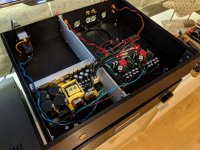
I'm running the double WHAMMY boards as a pre-amp for Purifi class-D power amps. As these power modules like a good drive I'm using the circuits as is and did not include any more series output resistance than the already existing 10ohm resistors in MOSFET stage.
I have also short circuited both C1/C5 and C26/C27... as no capacitor is better than arguing which capacitor sounds better. DC offset at power amp output is < 8mV, which I deem perfectly fine and safe.
Switching the output via a 6.5mm plug contacts should also be just fine.
I couldn’t wait for the pcb to arrive so I started the project with parts I had already laying around. I made this one dual op amp because I had a couple of opa604’s and will do tests with opamps like the AD797, OPA1611.
Have to finish the housing (cosmetic), arrange the wiring and replace the potmeter with a blue Alps potmeter.
For now I’m listening with a HD6xx headphone, the thing is death silent, no hum whatsoever. Dynamic, open, detailed. I could listen for hours. Will do some comparison (by ear) with my Sjostrom QRV08 amp.
Attachments

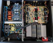
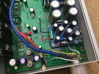
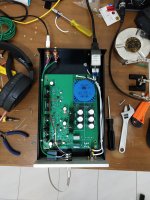
The PCB is a self drawn custom version - power goes in from mid edge of the board behind heat sinks.
The Super Regulators are exactly as per original schematic - just the heat sinks are 51mm tall if I recall correctly. No problems for those to run one 2 channel board each.
I have 4 MeanWell IRM-20-24 AC/DC converters powering the SuperRegulators. I had those coils in parts bin for year bought for a project I never did, so I though it would be good to use those.
We did a similar replica for my friend. He's version has WHAMMY in separate box and there we did not use the extra inductors. I did not see difference in measurements in the end.
Attachments

I received a Private Message from a member, who is considering building a modified WHAMMY that includes a switched headphone jack and "preamp output" RCA connectors. S/he asked a bunch of questions which, in my opinion, are best discussed in the Forum where everybody can participate and learn.
The builder is thinking about using an arrangement similar to the one used by the Noir headphone amp from the DIYA Store; schematic below.
In this arrangement, the switched headphone jack (a Neutrik NMJ6HFD2) connects the WHAMMY outputs to the RCA jacks if, and only if, there is no headphone plug inserted. However, when a headphone plug IS inserted, the WHAMMY outputs are disconnected from the RCA jacks; the signal path is interrupted.
I'm sure the builder would love to have the opinions of other Forum members, about this sort of idea. Perhaps including, but certainly not limited to,
- Is this a reasonable idea? Does it have hidden (or obvious!) flaws?
- Are the 100 ohm resistors really necessary? Or can they be eliminated? What's the optimum resistance value?
- Are the 220K ohm resistors really necessary? What's the optimum resistance value?
- What are some other options for switching headphone jack functions? Are they preferable to this one?
Thank you to everyone!
I've built 2 Whammys with the Noir circuit that uses a switching HP jack and RCA outputs. Works fine in my experience.
As a preamp, some series load is desirable for safety in event of a shorted RCA jack. Also some input circuits may not play well with a 10 ohm (relatively) high current source. I typically use 100 to 150 ohms. It seems that the only reason to reduce it would be if the next stage had a very low input impedance, such as a passive EQ filter. I believe 100 ohms would be inaudible with anything in the typical 10K or higher input impedance range since you are talking a 1% loss or less to the voltage divider.
220K in parallel with the RCA outputs protects the downstream device from an open cable which could introduce noise or hum to its input when not connected to the Whammy output. That condition does not exist with a dedicated preamp that is always connected. Again, 220K seems like a nice compromise between how much it is loading the downstream input impedance yet still providing attenuation while headphones are in use.
It intuitively seems that if you add series and parallel resistance, you ideally want a switching jack that removes those loads from the HP output when headphones are connected. But that load (100 ohms in series with 220K to ground) would probably not affect the headphone sound when connected in parallel with the headphone load. I don't know for sure.
The headphones, however, also might affect the sound of the preamp signal going to the downstream device if trying to have the Whammy use both outputs at the same time. I say "might" as I again have no direct experience in that scenario. So it may be that the switching jack operates only for convenience and could be eliminated if desired.
I received a Private Message from a member, who is considering building a modified WHAMMY that includes a switched headphone jack and "preamp output" RCA connectors. S/he asked a bunch of questions which, in my opinion, are best discussed in the Forum where everybody can participate and learn.
The builder is thinking about using an arrangement similar to the one used by the Noir headphone amp from the DIYA Store; schematic below.
In this arrangement, the switched headphone jack (a Neutrik NMJ6HFD2) connects the WHAMMY outputs to the RCA jacks if, and only if, there is no headphone plug inserted. However, when a headphone plug IS inserted, the WHAMMY outputs are disconnected from the RCA jacks; the signal path is interrupted.
I'm sure the builder would love to have the opinions of other Forum members, about this sort of idea. Perhaps including, but certainly not limited to,
- Is this a reasonable idea? Does it have hidden (or obvious!) flaws?
- Are the 100 ohm resistors really necessary? Or can they be eliminated? What's the optimum resistance value?
- Are the 220K ohm resistors really necessary? What's the optimum resistance value?
- What are some other options for switching headphone jack functions? Are they preferable to this one?
Thank you to everyone!
This is exactly how I built and use my first Whammy. I didn't need to make any mods on the RCA outputs when using it as a preamp - you unplug the headphone jack and the jack switches the output to the other output, which I connected to RCAs on the back.
It may help explaining better the reasons why *a* resistance is needed on the inputs/outputs. I did this experiment myself recently by eliminating them and seeing how things behaved. One suggestion is to insert a potentiometer to experiment with variable values. Thats half the fun of DIY!
There were discussions about how to hook up multiple inputs on diyaudio but perhaps this was on the Noir Preamp thread - can't recall. Options amounted to either a physical switch - control knob on the front connected by a rod to the actual switch on the rear that switches in one of the inputs. The other option is a relay/transistor configuration triggered by a "remote" push button on the front panel that is used to activate the relays that engage one of the rear input RCAs. This is how remote-controlled options work too. I am actually investigating this myself so I'd love to hear what others are doing.
Sounds good!
Just completed this about 2 days ago and have been playing with it! It's temporary until my chassis arrives 3 days later. Will be attempting to mount this horizontally and use a shaft extender to the potentiometer. Am using a RS rebranded Talema (i think) 18v transformer and ELNA Silmics
I forgot to lay down my capacitors near the op-amps when soldering. Guess i'm making do for now lol.
I have on hand the chinese discrete HDAM (for some reasons it's noisy and oscillates for about 10 seconds before it is stable). Tried the stock NJM4580 and the OPA2132 (really liking it for now). Waiting for my SOIC-DIP8 so I could try the OPA1612AID and also dual-to-mono adapter for my OPA627bp. Trying to bug my friend to sell me his LME49990 (apparently it's very good?). Tried the LM6172, it heats up quite quickly and makes weird noises (checked the datasheet it says it can take up to 36V?). Anyhow I guess it's not suitable.
Thanks everyone! This has been really helpful. Am happy with this so far!
I have some extra parts and will be attempting a second build with UKA Nichicon at C12, C17, C22 and C25 and some multicomp resistors as these are the only capacitors that are available at this part of the world for me that are audio grade (can only buy from Farnell or Radioshack). I had alot of trouble with customs and DHL when i was receiving my parts from Mouser for my 1st build and it was frustrating as I got charged alot of other fees.
Attachments
Decided to have another tinker with my Whammy whilst waiting for parts for other projects.
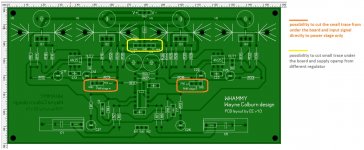
This time I have installed a Cap Multiplier supply by Mark Johnson and Prasi. The last 3300uF caps in the PSU were removed but keeping the 5.1R's under the whammy board still keeps the circuit as CRCRC before the multiplier circuit, the final C is 1000uF on the cap mx board.
DC output is 16.5V on both rails. What can I say, it works perfectly and sounds great.
If anyone is interested to try this I have some Cap MX boards spare, part built with all smd components, you just need the through hole components to finish.
Also, after months of waiting to find a pair at the right price, I have snagged some Focal Elear phones. They have blown my tiny mind. Absolutely stunning headphones, the OPA627's sound fantastic and the LT1128's really shine with the Elear's.
Attachments
That looks very neat indeed.Decided to have another tinker with my Whammy whilst waiting for parts for other projects.
This time I have installed a Cap Multiplier supply by Mark Johnson and Prasi. The last 3300uF caps in the PSU were removed but keeping the 5.1R's under the whammy board still keeps the circuit as CRCRC before the multiplier circuit, the final C is 1000uF on the cap mx board.
DC output is 16.5V on both rails. What can I say, it works perfectly and sounds great.
If anyone is interested to try this I have some Cap MX boards spare, part built with all smd components, you just need the through hole components to finish.
Also, after months of waiting to find a pair at the right price, I have snagged some Focal Elear phones. They have blown my tiny mind. Absolutely stunning headphones, the OPA627's sound fantastic and the LT1128's really shine with the Elear's.
I'd be interested in one of those cap multiplier PCB please.
Just finished my WHAMMY!
Thanks Wayne and 6L6.
Wornderful project!!!
I've used the AD823ANZ opamp.
Cabling is a Van Damme starquad silver plated cable. Used double cores for signal and shield for ground.
Dc offset is 0.1 mV in both channels


Thanks Wayne and 6L6.
Wornderful project!!!
I've used the AD823ANZ opamp.
Cabling is a Van Damme starquad silver plated cable. Used double cores for signal and shield for ground.
Dc offset is 0.1 mV in both channels
I made a previous post about noise in the right channel when using dirty stepped sine wave from an inverter. This was totally fixed after using shielded cables connecting to the line in. I assume it was picking up noise of the transformer caused by the dirty sine wave.
Super cool. I would love to try one for sure. Question: Is there room for the heat sinks for the LMs? The board positioning looks tight.
Decided to have another tinker with my Whammy whilst waiting for parts for other projects.
This time I have installed a Cap Multiplier supply by Mark Johnson and Prasi. The last 3300uF caps in the PSU were removed but keeping the 5.1R's under the whammy board still keeps the circuit as CRCRC before the multiplier circuit, the final C is 1000uF on the cap mx board.
DC output is 16.5V on both rails. What can I say, it works perfectly and sounds great.
If anyone is interested to try this I have some Cap MX boards spare, part built with all smd components, you just need the through hole components to finish.
Also, after months of waiting to find a pair at the right price, I have snagged some Focal Elear phones. They have blown my tiny mind. Absolutely stunning headphones, the OPA627's sound fantastic and the LT1128's really shine with the Elear's.
Super cool. I would love to try one for sure. Question: Is there room for the heat sinks for the LMs? The board positioning looks tight.
Yes I'd say so Thomas, you could run the CapMX and the standard regs from the CRC supply, the regs could power the back end while the MX board powers the op-amp for instance.
PM sent.
Edit - all the current batch of Cap MX boards have been taken, I will certainly order more kits soon.
Last edited:
Another Whammy lives! Sounds very good. Love the top n bottom extensions. Very crisp and airy. Makes my old/obsolete Sennheiser HD525 sound new again.
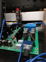
Can anyone suggest a way to allow plugging/unplugging headphones while the pre out is being used? I'm using the switching headphone jack.
With it hooked to a power amp, it will screech very loudly when I plug/unplug headphones. This doesn't happen with my other amp build.
Can anyone suggest a way to allow plugging/unplugging headphones while the pre out is being used? I'm using the switching headphone jack.
With it hooked to a power amp, it will screech very loudly when I plug/unplug headphones. This doesn't happen with my other amp build.
Attachments
One option to try is to leave the ground wire going to RCA connected to WHAMMY ground constantly and only letting the 6.5mm plug connect/disconnect the L/R signals. At moment the ground gets disconnected also and the amp might not like that as you create signal spikes that can be avoided.
One option to try is to leave the ground wire going to RCA connected to WHAMMY ground constantly and only letting the 6.5mm plug connect/disconnect the L/R signals. At moment the ground gets disconnected also and the amp might not like that as you create signal spikes that can be avoided.
D'oh! How did I miss that obvious thing. Connected the rca in/out with a scrap wire and it only crackled a bit when plugging the headphone jack.
Mark, why didn't you tap from one of the rectifier diodes on the board instead?Anything bad if we do this? Also what value is the resistor?I wanted instant-on, instant-off behavior from my front panel LED, so I connected it straight to the AC from the transformer (with a couple of other safety items). It did exactly what I wanted: no graaaaaaaaadual dimming as the supply filter caps slooooooowly discharge.
See post #1530 of this thread for a photo.
- Home
- Amplifiers
- Pass Labs
- "WHAMMY" Pass DIY headphone amp guide