Yes, unfortunately I know that. A long time ago, the two regulators remained as a pair with the smallest possible voltage difference.7800/7900 regulators have a fairly wide output specification. They all are a little different. Don't worry about it. 😀
Motorola regulators used to be among the best, but the 7815 was always 0.2-0.5 volts low and the 7915 was 0.2-0.4 volts too much.
I would like to omit C1 and C5 and would like very same voltages for the + and -.
Can you put a resistor in front of the LED to adjust the voltage?
I could also use LEDs with different forward voltages, but I don't have any here right now.
Is there another (good) way?
Hi John Ess,
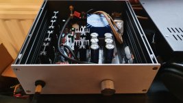
Excellent chassis choice. I went for the exact same and it leaves a nice reasonnable headroom around.
On my side, i got rid of the input caps (circuit seems to already eliminate dc on output with +0,7 and +0.4mV), and beefed up the heatsink (40%taller), and ended up with a but more output bias 82mA instead of default 60mA).
It sounds faboulus.
Op amp rolling also brings insteresting ways of optimizing system synergy.
Attachments
Last edited:
I almost went that route after looking around for better quality caps that would fit. Then I found these Mundorf MCap Supremes that just barely fit without too much craziness. Think I'll just leave them in place, as I really couldn't ask for any more transparency. And they weren't crazy money either from Parts Connexion. My only hang up with the chassis deals with the hole for the volume control. Gather that it might be better to not attach the control to the front plate. Thinking I'll adjust the height of the board so that the shaft is on the horizontal center line of the plate and drill just large enough to accommodate the shaft thread and all. I have no means of counter boring. The other thought would involve replacing the front plate with 2 identical pieces of black plastic stacked together...one with a hole to fit the knob, one without. I can get plastic fabricated pretty easily.
Roland -
Some possibilities;
Buy 100 of each 7815 and 7915 and measure them all, use the 2 that are a match and sell the rest or keep for future projects,
Use a discrete replacement that has much tighter output voltage tolerance - Sparkos Labs, Inc. audio power supply discrete voltage regulators
You suggested trimming by changing the LED, that’s a great solution. You can get large boxes on amazon for very little money. https://www.amazon.com/dp/B078RK19J2/ref=cm_sw_em_r_mt_dp_U_C5gQEbY4MZZ0H
Or just recall that the DC offset is a function of the opamp’s input offset multiplied by the DC gain of the circuit, which if you install C26 and C27, will be 1. So it’s really going to be up to the individual opamp more than any other variable.
Last edited:
Excellent!! Member 6L6 has listed quite a few tremendous, workable ideas.
Allow me to mention one other: Engineer a pair of drop in replacements. The positive one uses an LM317 adjustable voltage regulator IC, and includes a 25-turn trimpot which allows you to dial the output with millivolt accuracy. The negative one uses an LM337 adjustable voltage regulator IC, and includes another 25-turn trimpot.
Put these on little daughter boards in a similar way to the Sparkos regulators mentioned above.
Dial them to your heart's content. Done!
@6L6
Thanks for your help,
as I said, my Motorola MC7815CV and MC7915CV come from such a campaign in which we selected over 200 pairs, but that was almost 20 years ago ...
Next time I will order and measure a few from Mouser.
I will test that with the different LEDs soon and will post the result here. Has anyone tested how large the forward voltage spread of a type is?
I had already looked at the voltage regulators from Sparkos, but I would first test an external board with LM317 / 337 or the SUPER REGULATOR power supply from the DIY audio store.
But I will ask Sparkos if they are suitable for this large voltage difference. Maybe I'll test the parts ...
I am not a big friend of interventions to remove DC offset, so the coupling capacitors should also be removed. For me it is always the best solution to prevent a problem than to have to solve it afterwards. However, I am also a very lazy person... 😀
the LM317 / 337 could also be placed directly on the board with a small circuit, but I will first order and try out other 78/7915 and LEDs.
Then I want to test whether a "better" power supply really has an effect and makes the Whammy even "quieter", or not 😉
Thanks for your help,
as I said, my Motorola MC7815CV and MC7915CV come from such a campaign in which we selected over 200 pairs, but that was almost 20 years ago ...
Next time I will order and measure a few from Mouser.
I will test that with the different LEDs soon and will post the result here. Has anyone tested how large the forward voltage spread of a type is?
I had already looked at the voltage regulators from Sparkos, but I would first test an external board with LM317 / 337 or the SUPER REGULATOR power supply from the DIY audio store.
But I will ask Sparkos if they are suitable for this large voltage difference. Maybe I'll test the parts ...
I am not a big friend of interventions to remove DC offset, so the coupling capacitors should also be removed. For me it is always the best solution to prevent a problem than to have to solve it afterwards. However, I am also a very lazy person... 😀
Thanks for the tip,Allow me to mention one other: Engineer a pair of drop in replacements. The positive one uses an LM317 adjustable voltage regulator IC, and includes a 25-turn trimpot which allows you to dial the output with millivolt accuracy. The negative one uses an LM337 adjustable voltage regulator IC, and includes another 25-turn trimpot.
Put these on little daughter boards in a similar way to the Sparkos regulators mentioned above.
Dial them to your heart's content. Done!
the LM317 / 337 could also be placed directly on the board with a small circuit, but I will first order and try out other 78/7915 and LEDs.
Then I want to test whether a "better" power supply really has an effect and makes the Whammy even "quieter", or not 😉
Last edited:
I believe the 7815 has a peak current of 2.2 amps, but the LM317 has a peak current of 1.5 amps.
I don't think the whammy would draw that much anyway, but it's worth pointing out.
I don't think the whammy would draw that much anyway, but it's worth pointing out.
For those who want (|Vout+|) minus (|Vout-|) to be a small number of microvolts, the tracking regulator circuit architecture may be appropriate. It uses more components and it requires a greater amount of circuit design effort than "just copy what you see in the datasheet". In exchange for this additional effort, you get a feedback control system which actively controls Vout- to be exactly -1.0 times Vout+. Just exactly what is wanted.
The blocks in the block diagram are:
1. Generate a stable constant voltage VCONST which is independent of temperature, time, the input voltage, and the output current. Maybe a cascoded current source, driving an LM329 (for example).
2. Use an opamp and a potentiometer to generate VREF, a voltage which is some number K times VCONST. Usually (0.5 <= K <= 2.0). Dialling the pot changes the value of K, which in turn changes VREF.
3. Build a positive regulator whose output voltage is N x VREF for some fixed number N.
4. Build a negative regulator whose output voltage is -1.000 x VPOS.
Eureka! block #4 ensures that Vout+ and Vout- have the same magnitude. You can include trimpots to cancel out any offsets in block #4, and make sure that the constant of proportionality really IS -1.000. Even when using relatively crappy tolerance (1%) resistors.
Block #2 allows you to simultaneously dial Vout+ and Vout- up and down, together. They track one another; they're always equal and opposite. Hence the name, tracking regulator.
Keep in mind, this is certainly not a simple job, especially when you consider frequency compensation / stability. But for those who just gotta have those precious microvolts of matching, it's fifty or a hundred hours, well spent.
For those who want (|Vout+|) minus (|Vout-|) to be a small number of microvolts, the tracking regulator circuit architecture may be appropriate. It uses more components and it requires a greater amount of circuit design effort than "just copy what you see in the datasheet". In exchange for this additional effort, you get a feedback control system which actively controls Vout- to be exactly -1.0 times Vout+. Just exactly what is wanted.
The blocks in the block diagram are:
1. Generate a stable constant voltage VCONST which is independent of temperature, time, the input voltage, and the output current. Maybe a cascoded current source, driving an LM329 (for example).
2. Use an opamp and a potentiometer to generate VREF, a voltage which is some number K times VCONST. Usually (0.5 <= K <= 2.0). Dialling the pot changes the value of K, which in turn changes VREF.
3. Build a positive regulator whose output voltage is N x VREF for some fixed number N.
4. Build a negative regulator whose output voltage is -1.000 x VPOS.
Eureka! block #4 ensures that Vout+ and Vout- have the same magnitude. You can include trimpots to cancel out any offsets in block #4, and make sure that the constant of proportionality really IS -1.000. Even when using relatively crappy tolerance (1%) resistors.
Block #2 allows you to simultaneously dial Vout+ and Vout- up and down, together. They track one another; they're always equal and opposite. Hence the name, tracking regulator.
Keep in mind, this is certainly not a simple job, especially when you consider frequency compensation / stability. But for those who just gotta have those precious microvolts of matching, it's fifty or a hundred hours, well spent.
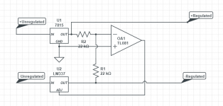
I suppose something like this could also be possible, just an inverted voltage follower. Then any positive/negative voltage regulator could be used and the negative output would just be inverted positive voltage out(This schematic isn't complete and is missing complimentary components):
Attachments
You could use the resistor option instead of the led and stand a multi turn pot up in the two holes.
For those who want (|Vout+|) minus (|Vout-|) to be a small number of microvolts, the tracking regulator circuit architecture may be appropriate. It uses more components and it requires a greater amount of circuit design effort than "just copy what you see in the datasheet". In exchange for this additional effort, you get a feedback control system which actively controls Vout- to be exactly -1.0 times Vout+. Just exactly what is wanted.
The blocks in the block diagram are....
Thanks for the effort, but that is beyond my ability. the normal voltage control with LM317 / 337 is not a problem, but from that I have too little clue.
Do you have a link to an example or a diagram?
I still have a board with LM317 / 337 and an LF353, which I will test on the Whammy in the next few weeks.
Hello Wayne, first of all I have to say that I am very excited about this little amplifier.You could use the resistor option instead of the led and stand a multi turn pot up in the two holes.
The first hearing test was very good and at the weekend I will compare it a little.
I find the solution with the LED as voltage reference very exciting and have already ordered LEDs from 1.6 - 2.4v in 0.05 - 0.1v steps to set them.😎
Hello thomasnadeau,
what's wrong with the version with MU metal?
It still allows for some stray fields to get out. A metal can does the trick.
Also, I was poking around at some ACA articles online and realized that Antek does well metal cans for their shielded (mu metal ring) and non-shielded transformers, but you have to look elsewhere:
Misc - Steel Cases - AnTek Products Corp
The good news it that you can order them after-the-fact, so if you are like me, and ordered a regular one previously, you can add this.
Sorry if this has been asked before, but I have 2 questions.
1. What is the power output of this amp? I saw in head-fi someone mentioned 300-400mW.
2. Any recommendations of a stepped pot/attenuator for gain settings 1k-10k? I supposed this would be a linear instead of a log, am I right?
Thanks.
1. What is the power output of this amp? I saw in head-fi someone mentioned 300-400mW.
2. Any recommendations of a stepped pot/attenuator for gain settings 1k-10k? I supposed this would be a linear instead of a log, am I right?
Thanks.
It still allows for some stray fields to get out. A metal can does the trick.
Also, I was poking around at some ACA articles online and realized that Antek does well metal cans for their shielded (mu metal ring) and non-shielded transformers, but you have to look elsewhere:
Misc - Steel Cases - AnTek Products Corp
The good news it that you can order them after-the-fact, so if you are like me, and ordered a regular one previously, you can add this.
Hello Thomasnadeau,
I can not comprehend that.
With static and magnetic shielding, the attenuation of MU metal is far above that of steel and copper, approx. 20db.
Steel is only used for cost reasons and because it is much easier to process than MU metal.
The best is a toroidal transformer cast in a MU metal cup.
Almost $ 40 is a proud price for such a steel cup.
In steel trade you pay about $ 3 - 4, - for a 100mm section of a 100mm steel tube with 3mm wall thickness. If you can't weld, you can simply stick a steel plate on top and stir in fine steel shavings into the epoxy resin adhesive. Technically, you won't measure any difference in shielding.
And lined with copper foil on the inside. It is definitely a much cheaper solution than MU Metal.
Last edited:
Trafo
https://export.farnell.com/multicomp/mcfe030-18/transformer-30va-2-x-18v/dp/9531742
I've been hunting high and low for a shielded (steel can) transformer (toroid) for the Whammy project and wanted to ask the forum for recommendations for North American sources. I have tried Antek, but they only have a shielded (surrounding the toroid with mu metal) option not a on steel can type. Both Plitron's and Toroid's websites seem to be messed up right now (any search for products returns nothing or a circular reference). I've tried Mouser and Digikey but they seem to only have similar options. Those are the only places I've ordered xformers from in North America and have struck out so I was hoping someone here could recommend some options.
https://export.farnell.com/multicomp/mcfe030-18/transformer-30va-2-x-18v/dp/9531742
These guys might have something that will work..EMF Safety Superstore - Electromagnetic Field Meters and Shielding
My Whammy got ready tonight and works fine.
However, I have slightly different regulated voltages on the + / - rail, + = 16.63v and - = 16.91v.
I built the Configuration 2 - “LED reference” and used Motorola MC7815CV / MC7915CV as a voltage regulator.
I measured the regulator before installation and the 7815 has an output voltage of 14.91v and the 7915 has 15.19v, so it is clear that the difference of +/- comes from the voltage regulator.
What can I do to get the same +/- voltage? Without filtering voltage regulators.
Hi Roland,
You shouldn't be concerned about the small differences in your rail voltages.
Your + rail will start to clip sooner than your - rail as the audio level is increased but that isn't a practical problem since we don't listen to these amplifiers anywhere near the point where they stop amplifying and start clipping.
Mike
Hi Mike, I'm not worried because I've measured worse for expensive commercial products. Of course also with cheap ones 😀.
The difference in voltages is the same in all states. Nothing changes, whether at idle or under "high" load.
I just want to have a perfect symmetrical as possible voltage at the OP Amp and the amplifier to produce also no unnecessary DC offset.
It is a mixture of pedantry and fun in the matter.
Last edited:
- Home
- Amplifiers
- Pass Labs
- "WHAMMY" Pass DIY headphone amp guide