Got this when sampling for chromatic aberration. Acceptable at f2.8 with a little extra from LR. Though yeah, exposure layering with aperture variation would be the better option here as it gives more data about the scene.

NiceGot this when sampling for chromatic aberration. Acceptable at f2.8 with a little extra from LR. Though yeah, exposure layering with aperture variation would be the better option here as it gives more data about the scene.View attachment 1011860
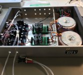
Let's see the SMD JFET's, I used magnifying glass on mine, would like to see a photo or two. On two of the three PCB's I built, two had poor solder joint on one leg of one JFET. Never saw it using the glass.
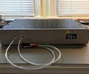
And do over is... done. Haven't dropped it into the main system yet. Cables shooting out the front there is maybe a bit odd, but that's where my amps live and eliminates a pair of male and female RCA connectors, and a much shorter run overall. Some people think power supplies matter.... well this thing is about 95% PS so we'll see.
Attachments
Failed on power up! Horrible high level nasty static / pink noise on both channels. I had some extra load resistors on the ouputs of these Superreg's because I had read that the performance is better if you give them some real work to do. But I failed to apply this added load in the proper way. Removed those parts and it's fine now. Looking back, I should have built my gain stage with the optional larger output parts and pumped up the current there. But it's OK, sounds good anyhow. Best sound description... "like a babbling brook along with the smell of the crisp alpine air...." 😊😊 Really though, we'll see if I prefer this configuration after my ears burn-in...
Ok so looking through this post...long one. Has anyone built this with the MUSE remote circuit?? Found some info on integrating that into this linestage.
I'm currently building a BA2018 with a 6-24 active crossover, I have the Academy Audio VCU with remote Muses volume control. Academy Audio has notes on how to integrate the VCU with the BA2018 line stage, it uses the Academy Audio power supply to operate the VCU and line stage at +-15 VDC.
I'm building using a VRDN power supply for the +-18 VDC for the line stage and then I built a +-15 vdc regulator to tap the VRDN for the VCU.
I've completed the remote power supply and umbilical cable, currently I'm drilling holes.
I'm building using a VRDN power supply for the +-18 VDC for the line stage and then I built a +-15 vdc regulator to tap the VRDN for the VCU.
I've completed the remote power supply and umbilical cable, currently I'm drilling holes.
Thank you for the feedback. I will follow any updates you have with this. Why two different power supplies instead of just using the 15vdc model?
Only 1 power supply, the VRDN set to +-18 vdc this feeds the line stage and a +-15 regulator for the VCU.
I did one with Lenny’s VCU. Page 144, post 2867. Also see page 149 for a discussion on powering the two.Ok so looking through this post...long one. Has anyone built this with the MUSE remote circuit?? Found some info on integrating that into this linestage.
Opted for a single +/-15Vdc supply that powers both the BA2018 and the VCU. The display is powered from the VCU board.
So I'm quite, quite, yes, quite confused by a lot of things in this kit because there's not a lot of clear information. It's all a bit sketchy, I guess. So...
Would it be considered offensive if I would offer to make a small PDF manual on parts identification, prep, the changes for the big transistors, some explanation, etcetera? I may eventually submit it to the DIYA help guides software thingy where the ACA is also posted.
Who is responsible for the PCB design, exactly? I've noticed that for no particular reason at all, there's shift in one of the boards. It's just about one to two milimeters.
I was also thinking whether it wouldn't be possible to make traces that link the input of the power, that are 'unjumpered' by default, and can be jumpered with solder/wire. It'd look clean, if done on the bottom, where there's plenty of space for thick tracks.
Just thinking out loud here though. Shoot if any of this has already been done!
Wow, just the opposite of what I thought! Interesting.So I'm quite, quite, yes, quite confused by a lot of things in this kit because there's not a lot of clear information.
Still not right. Noise in both channels. Left channel, noticeable hiss a foot or so from the speaker, and several feet from the right. Not exactly "Super" results... A little discouraged, but I guess I will learn something one way or another after I try some things. Won't be quick though. Really need a scope here at the house for troubleshooting this sort of thing, oscillation I assume. Regs probably don't like those .1uF decouplers on my purple boards for one thing. Might just yank everything apart and start over. Do the bigger outputs and increased current, get proper power transformers and drop the voltage (@25V rails now), etc.
William, can you list me quickly some of these parameters regarding your current results?Still not right. Noise in both channels. Left channel, noticeable hiss a foot or so from the speaker, and several feet from the right. Not exactly "Super" results... A little discouraged, but I guess I will learn something one way or another after I try some things. Won't be quick though. Really need a scope here at the house for troubleshooting this sort of thing, oscillation I assume. Regs probably don't like those .1uF decouplers on my purple boards for one thing. Might just yank everything apart and start over. Do the bigger outputs and increased current, get proper power transformers and drop the voltage (@25V rails now), etc.
I would like to know:
- Your (pos or neg) supply voltage
- Whether the two rails are measuring correctly in voltage in respect to ground and each other
- Whether you have tried tapping the board during operation
- What equipment you may have used to assemble the board
Could you also post some sharp and clear pictures of the board assembled as it is?
Have you undone all the wiring and redone it? These PCB terminal blocks are horrendous and notorious for their shitty contact, truth be told. I don't use them, I solder onto the board or use terminals that accept spades or JST XH2.54 connectors.
I doubt the regulators care at all about what decoupling is present, unless it's about too little. Modern solid state regulators care pretty much not at all, especially with quite consistent loads like these. If you're sure that it is the decoupling caps, then add some resistor load between GND and the pos/neg rails (GND to Vcc, GND to Vee.) Loading it down should then exacerbate or relieve the issue, depending on the cause.
I'm willing to help you out if we can come to a time to talk together.
Last edited:
The Jung/Didden Superreg is a different beast. It's an extremely low output impedance / very high performance / remote sensed regulator that requires that you pay attention to some things. You're right, most regs don't care too much about what you hang off of there, not this guy. It will absolutely oscillate if given the opportunity. Boards are assembled properly, voltages are fine. Definitely have a ground loop problem with the common ground on my raw DC supply and how I have it connected to the regs. I suspect fixing the ground loop and dumping the film decouplers on the client may straighten it out. If not, I'll try a screened and grounded sense wire and a 10-20 ohm series resistor at the load. Might do that anyhow.
If you don't have a sense wire yet, any sense wire will do better than sensing over the wire that's got the load. Just the sense wire not having a load basically eliminates any voltage drop, because the voltage drop comes from current limit from the wire impedance - and we don't have current. 🙂
Oh it's definitely got the sense wires. The 4 wire connection is a standard on a superreg. The problem I believe I've got is.... the regs are real close to the client (intentional), but there's not enough resistance / inductance with a 2.5 inch load wire to "hide" those .1 WIMA's I've always used.
- Home
- Amplifiers
- Pass Labs
- Wayne's BA 2018 linestage