Actually I think it is the chassis from the Noir Headphone amplifier kit in the store, with holes punched and silk screening done as well.
Correct. Treat the shield like it’s part of the chassis.
Copy, thanks Jim!
Actually I think it is the chassis from the Noir Headphone amplifier kit in the store, with holes punched and silk screening done as well.
Did they start with a Galaxy chassis? It looks like the several that I have. The side panels appear the same, and front and rear panels attach the same.
I guess they are all sort of similar. But if the member who asks is interested, it looks like a 2U Galaxy chassis, if you like that one.
Russellc
TOSHIBA 2SK209GR matching and soldering
Good evening,
in my todays nightshift at home, I matched 8 Toshiba 2SK209GR (out of a batch of 20).
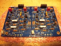
My pcbs for Waynes - BAF2015 - linestages arrived today - so -
solderslingin' time.
Let's try to solder those little critters on the board. I used my 'adhesive -tape-
technic': sticking the Jfets with adhesive tape to the pcb and make one solderjoint. Take the tape away and solder the other two legs. Worked pretty well.
But - don't solder too long or the tape will melt....🙄
One step done.
Sleep well!
Dirk
Good evening,
in my todays nightshift at home, I matched 8 Toshiba 2SK209GR (out of a batch of 20).
My pcbs for Waynes - BAF2015 - linestages arrived today - so -
solderslingin' time.
Let's try to solder those little critters on the board. I used my 'adhesive -tape-
technic': sticking the Jfets with adhesive tape to the pcb and make one solderjoint. Take the tape away and solder the other two legs. Worked pretty well.
But - don't solder too long or the tape will melt....🙄
One step done.
Sleep well!
Dirk
Attachments
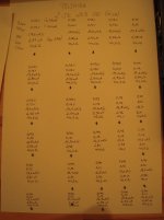
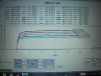
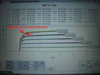
I don:t know how exactly my measurements are? 🙄 But the TOSHIBAS seem
to be very consistent from the reel....
Greets
Dirk 😀
Hello Dirk
Consistent they are, but regarding your plots use negative to zero Vgs. To compare lines match over a useful area, from near cut off to fully on. Like in the datasheets.
I run an example with Toshiba 2SK117GR (TO-92 NOS 3mA Idss at Vds 3V sample) for you to see the settings. Its electrically same spec type as 2SK209GR. Also lock own settings if for repeated sessions. Else they will be resetting after new identifications because of autoranging.
Attachments

Hello Salas,
I see what you do. Vgs from -0,3V to 0V. I locked the Vgs values. My experience is that DCA75pro is adjusting the Vgs automatically to different values.
Thanks for your tip!
Greets
Dirk
I see what you do. Vgs from -0,3V to 0V. I locked the Vgs values. My experience is that DCA75pro is adjusting the Vgs automatically to different values.
Thanks for your tip!
Greets
Dirk
You are welcome. I thought to tip you off because real matching is curves matching and you need area to see 😉
Hi guys. I am new to the forum, but have some experience building a pair of ACAs. I have read the PowerPoint and all 115 pages of this thread and seen it alluded to, but haven’t seen it answered clearly (maybe I missed it). I saw the schematic changes to go balanced in -> SE output. Ideally, I would like to have 1 balanced and 2 SE inputs going to 1 balanced and 1 SE output. Is that possible?
Thanks everyone for the great info so far. I’m really looking forward to hearing how this sounds with my ACAs.
Thanks everyone for the great info so far. I’m really looking forward to hearing how this sounds with my ACAs.
Is it possible to combine this with the Pearl 2 into one box and use the existing Pearl power supply to power both? I don't think I'll change my phono stage for a long time so it would be advantageous to combine the two. Dac's and computer audio change every year but RIAA stays the same.
Just throwing this out there.
If there is anybody willing to solder the 209s for me, I will be happy to pay for it.
In the first time in my 59 years I have run into something I am unable to do, and it kind of sucks actually.
If there is anybody willing to solder the 209s for me, I will be happy to pay for it.
In the first time in my 59 years I have run into something I am unable to do, and it kind of sucks actually.
building Waynes linestage
Hello members,
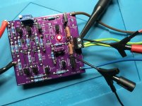
today I continued working on Waynes linestage. I was testing and matching a lot of KSA992 and KCA1845. I think I was in the wrong range? Salas will
see it.... 😉
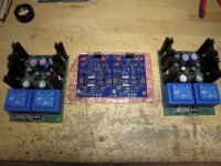
I have two +/-24V - PSUs I have built for a phono-stage. I will try to use them.
Each can deliver 70mA. Should be enough for one channel? So I will be higher on the rails. We will see.
I would like to use Toshiba TTA004B / TTC004B in the outputstage (Q8/Q10).
Any hints how to bias the TOSHIBAs (R11/R12 value?). Sinilar like the Fairchild KSC2690/KSA1220 at around 15 Ohm/ 1W resistors for R11/R12?
Any hint is welcome.
Greets
Dirk 😕
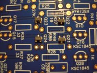
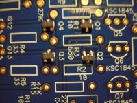
Hello members,
today I continued working on Waynes linestage. I was testing and matching a lot of KSA992 and KCA1845. I think I was in the wrong range? Salas will
see it.... 😉
I have two +/-24V - PSUs I have built for a phono-stage. I will try to use them.
Each can deliver 70mA. Should be enough for one channel? So I will be higher on the rails. We will see.
I would like to use Toshiba TTA004B / TTC004B in the outputstage (Q8/Q10).
Any hints how to bias the TOSHIBAs (R11/R12 value?). Sinilar like the Fairchild KSC2690/KSA1220 at around 15 Ohm/ 1W resistors for R11/R12?
Any hint is welcome.
Greets
Dirk 😕
Attachments

Hello members,
today I continued working on Waynes linestage. I was testing and matching a lot of KSA992 and KCA1845. I think I was in the wrong range? Salas will
see it.... 😉
I have two +/-24V - PSUs I have built for a phono-stage. I will try to use them.
Each can deliver 70mA. Should be enough for one channel? So I will be higher on the rails. We will see.
I would like to use Toshiba TTA004B / TTC004B in the outputstage (Q8/Q10).
Any hints how to bias the TOSHIBAs (R11/R12 value?). Sinilar like the Fairchild KSC2690/KSA1220 at around 15 Ohm/ 1W resistors for R11/R12?
Any hint is welcome.
Greets
Dirk 😕
Hello, R11/R12 15Ohm is perfect. 🙂
Hallo Dirk,
I built mine with the Toshibas as big outputs as well. I used 15R Dale RN60 for R11 and R12. I actually have them socketed to later try different values ... so far haven't changed them, however 😛
Normally I use Yageo's, most often bought at Reichelt. A 1W metal film resistor should be fine. I settled on +/- 18V for the rails, though.
Have fun building and listening, Claas
Attachments
Last edited:
to chede
I was also thinking to prolong the legs of the BJTs (with short wires) and mount them on a heatsink.
I think I will solder the bias resistors from the underside of the pcb - easier to exchange and play with values.... But I will try 15 Ohm.
Good night!
Dirk
I was also thinking to prolong the legs of the BJTs (with short wires) and mount them on a heatsink.
I think I will solder the bias resistors from the underside of the pcb - easier to exchange and play with values.... But I will try 15 Ohm.
Good night!
Dirk
I have used +/- 24 with the small outputs and 27R R11 R12 - it works beautifully.
Bigger output devices should have more current, change to 15R as suggested and enjoy!
PSU voltage is very forgiving, 15-24 will work well. I have used 15, 18, 24V all successfully.
Bigger output devices should have more current, change to 15R as suggested and enjoy!
PSU voltage is very forgiving, 15-24 will work well. I have used 15, 18, 24V all successfully.
to 6L6
Thanks 6L6,
I will use those +/+ 24 V PSUs. And I can make it Dual-mono then.
Greets
Dirk
Thanks 6L6,
I will use those +/+ 24 V PSUs. And I can make it Dual-mono then.
Greets
Dirk
- Home
- Amplifiers
- Pass Labs
- Wayne's BA 2018 linestage