You should try and do the same measurements..
I can but the measurements will be the same. If a load introduced ripple there would be no point filtering the power supply. 🙂 I will check it though anyway just to satisfy my curious mind.
Maybe Wayne could chime in and confirm if the ripple measurements were the same on the PSU under load as they were without a load when he designed the Whammy.
Regards
Gareth
Ripple is caused by (a) load current discharging the filter capacitors -- this creates the downward slope half of the ripple; and (b) diode current recharging the filter capacitors -- this creates the upward slope half of the ripple.
When load current is zero, there is no downward slope. Thus there is no upward slope. Thus there is no ripple.
If the power supply itself contains elements (bleeder resistors etc) which draw load current, then these elements cause a small amount of ripple.
When load current is zero, there is no downward slope. Thus there is no upward slope. Thus there is no ripple.
If the power supply itself contains elements (bleeder resistors etc) which draw load current, then these elements cause a small amount of ripple.
Hi Gareth, as per your post #1037 I would be interested in 2 of the PSU boards if you organize a group buy. At this stage , do you have a BOM or parts list that you can post, thanks.
Regards,
Gary..
Regards,
Gary..
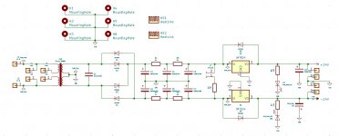
CRCRC Linear Regulated PSU
DUAL RAIL POS/NEG - 78xx / 79xx
PN001 (REV. A)
DigiKey BOM List:
--------------------
399-5464-ND x1 Kemet R46KN322000M1M 0.22uf/250V Snubber Capacitor (X2 Rated Polypropylene)
493-1883-ND x6 Nichicon (UPW) UPW1V332MHD 3300uf/35v 20% Capacitor
1N4004-TPMSCT-ND x6 Micro Commercial Co 1N4004-TP Rectifier Diode 400v/1A
5.1ZCT-ND x4 Yageo FMP200JR-52-5R1 5.1 ohm 2W 5% Resistor
MC7815CTGOS-ND x1 ON Semi. MC7815CTG 7815 15v Positive Regulator
MC7915CTGOS-ND x1 ON Semi. MC7915CTG 7915 15v Negative Regulator
HS352-ND x2 Aavid 531102B02500G Black Extruded Radial Fin Heatsinks
2.80KXBK-ND x1 Yageo 2.8k 1/4W 1% Resistor - MFR-25FBF52-2K8
1.00KXBK-ND x2 Yageo 1.0k 1/4W 1% Resistor - MFR-25FBF52-1K
516-1792-1-ND x2 Broadcom HLMP-1790-A0002 3mm / 2.3mcd / 1.9v / 2mA Green LED
493-1864-ND x2 Nichicon (UPW) UPW1V221MPD6 220uf/35v 20% Capacitor
As the LED on the regulator output is for dummy load only and NOT to set a reference voltage you can pretty much use any LED colour you like.
------------------------------------------------------------------------------------------------------
If you want better resistors then you can order the Vishay ones below if they are available:
------------------------------------------------------------------------------------------------------
RN55D2801FB14-ND x1 Vishay Dale RN55D2801FB14 2.8k 1/8W 1% Resistor (Military, MIL-R-10509/7)
RN55D1001FB14-ND x2 Vishay Dale RN55D1001FB14 1.0k 1/8W 1% Resistor (Military, MIL-R-10509/7)
PPC5.1W-2CT-ND x2 Vishay BC Components PR02000205108JR500 5.1 ohm 2W 5% Resistor
Transformers:
-----------------
Remember: DC current is approx 1.414 times AC current.
****************************************************************
*** Be careful when choosing transformer! DO NOT EXCEED 1A on the PSU! ***
****************************************************************
The following are good if using 24v Regulators:
TE2261-ND x1 Amgis L01-6365 25VA/22v Transformer (568mA per output)
1295-1079-ND x1 Talema 70065K 25VA/22v Transformer (568mA per output)
Talema Transformer Catalog:
---------------------------
http://www.talema.com/uploads/documents/product-datasheets/Transformer Catalog.pdf
Board Dimensions:
-----------------
L-219.202 W-94.742
Thanks for the info Gareth, much appreciated. I will keep my eyes open for details from you on a GB, thanks.
Gary..
Gary..
Hi again Gareth, to complete the info, can you post the schematic as well - put me down for 2 of these pcb's, thanks again.
Gary..
Gary..
The board size is 218mm x 94mm.
Gareth:
Now I'm being greedy, but is there any chance the board can be shrunk down a bit?
Regards,
Scott
Gareth:
Now I'm being greedy, but is there any chance the board can be shrunk down a bit?
Regards,
Scott
They have already been shipped to me from the fab house and I am awaiting delivery. When doing the layout I did the boards in as small footprint as I could physically muster but I'll look into tweaking the layout in a future board revision. 🙂
Spice model question
Modeled the BA2018 circuit in LTSpice but could not find any KSC1845 and KSA992 device models that actually worked in the circuit, so I used 2SC1845 and 2SA992 models.
Now Spice works but does not show any voltage gain between input and output. It does show around 57mA of current drawn from the power supply which seems in the ballpark. I suspect the red LED model I'm using may be wrong. Or maybe something else.
Does anyone have a spice model for a red LED that matches or comes close to the one currently in the design equipment list, the Lite-On LTL-1CHE ?
And since the 57mA seems reasonable, that rules out a single ended SMPS with a TLE2426 rail splitter for power supply but not a SMPS with the Goldpoint virtual ground circuit:
Virtual Ground Circuits from Voltage Regulators
Attachments
missing 10K from inside JFet gate to GND
ZM:
10K R17 was not in my model because it is shown in the published schematic apparently as a minus balanced input, and not explicitly shown as connected to ground.
That said, when I add it in and connect it to ground, the model works fine, showing about 4V out for 1V in.
So thank you, thank you for pointing this out. I will check the PCB and if CN2 pin 3 is not grounded I will jumper it to pin 2 which is supposed to be grounded according to the schematic.
I had mistakenly thought this circuit had a balanced input option.
Attachments
Last edited:
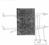
The stereo board can be set up balanced if you want just get two of them. You get both outputs that way.
I bought two boards to do exactly that. Anything other than connecting the grounds between boards necessary for balanced operation? Can an RCA input be in parallel to the XLR?
ZM:
10K R17 was not in my model because it is shown in the published schematic apparently as a minus balanced input, and not explicitly shown as connected to ground.
That said, when I add it in and connect it to ground, the model works fine, showing about 4V out for 1V in.
So thank you, thank you for pointing this out. I will check the PCB and if CN2 pin 3 is not grounded I will jumper it to pin 2 which is supposed to be grounded according to the schematic.
I had mistakenly thought this circuit had a balanced input option.
said 10K is necessary part of NFB loop, whatever you do with outer connection of it
for SE input , other end of 10K goes to GND
for Bal inputs, other end of 10K goes to neg input pad
in both cases that end of 10K is GND , real or virtual , speaking of NFB operation
Yes, I now understand balanced configuration uses both channels for a single signal. Just to confirm balanced hookup:
CN2-1: source +
CN2-2: jumpered to CN2-3 and to CN4-2 and connected to source shield. This ties the two board grounds together at the inputs (also tied via power supply ground, if using a common supply to both channels)
CN4-1: left open
CN4-3: source -
CN3-1: output +
CN3-2: possibly jumpered to CN5-2 although not necessary (output shield is typically single end connected to downstream balanced device input ground)
CN5-1: output -
Question: can balanced BA2018 output minus tolerate being grounded if connected to an unbalanced downstream device's input ground?
Folks:
I confess I'm struggling to understand the single-ended wiring configuration on these new boards. Can someone enlighten me?
Regards,
Scott
I confess I'm struggling to understand the single-ended wiring configuration on these new boards. Can someone enlighten me?
Regards,
Scott
- Home
- Amplifiers
- Pass Labs
- Wayne's BA 2018 linestage