
Currently away on a business trip. When I am home again in a few days, I have to dig out and post here my distortion measurements taken using REW.
Two channels on one board with isolated grounds and mounting holes and then the board edge connectors. There is a jumper to connect grounds if you want and use one board for balanced.
Hi Wayne, will you be posting a final schematic and a BOM to reflect any changes you might have made for this new stereo pcb?
Also when do you expect these to be available in the store?
Also when do you expect these to be available in the store?
Yes I will post the schematic soon. I have to send the data to Jim to check and they will order boards. It should be pretty soon.
Thanks for the quick reply Wayne, look forward to the final schematic so I can get parts organised.
Measurements of Wayne's BA 2018 linestage done with Focusrite 2i2 / REW
Well, in post #837 Wayne showed a measurement of distortion vs. output voltage.
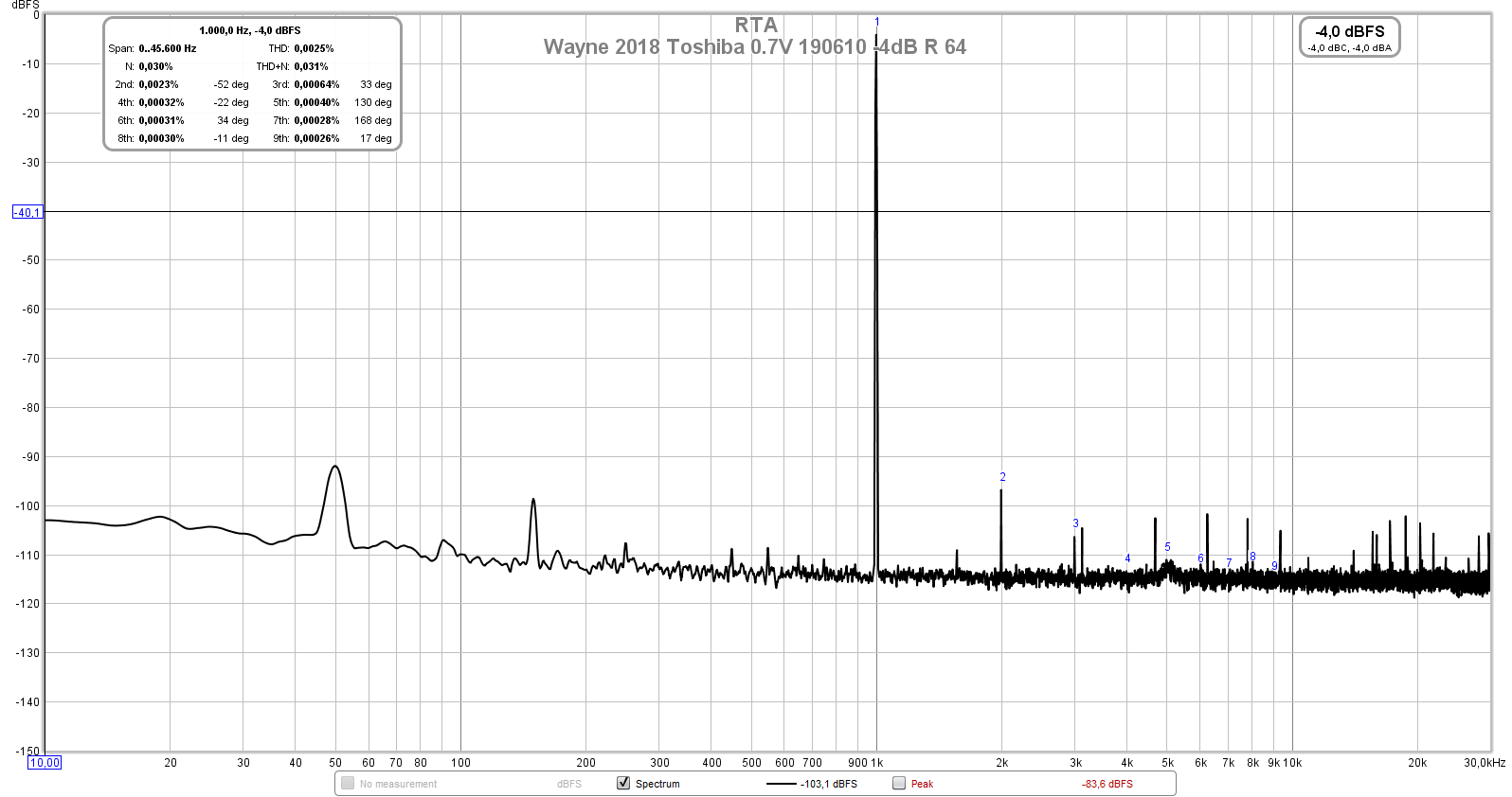
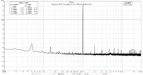
I dug out the pictures from my own measurements, done with a Focusrite 2i2 and REW. My BAF 2018 linestage (see my earlier posts in this thread) was built with Toshiba TTA004B and TTC004B as output transitors, 15R emitter resistors for the outputs, and a WIMA MKP10 1uF cap at the output.
All measurements are with 0.7V RMS input signal, attenuated by the preamp resistive divider circuitry the line stage is built.
So here it goes, 64 mV RMS output:
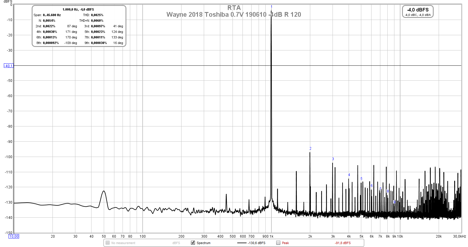
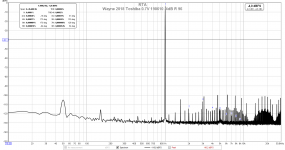
The next is 390 mV RMS output. Please ignore the hash to the right of the 1kHz fundamental, that's spuriae from the relay-based attenuator's control logic that is feeding through into the signal:

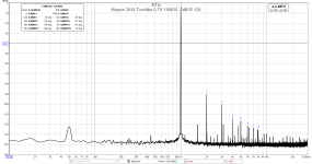
Now, 1.49 V RMS output voltage:
And, 2.63 V RMS output (no attenuation):

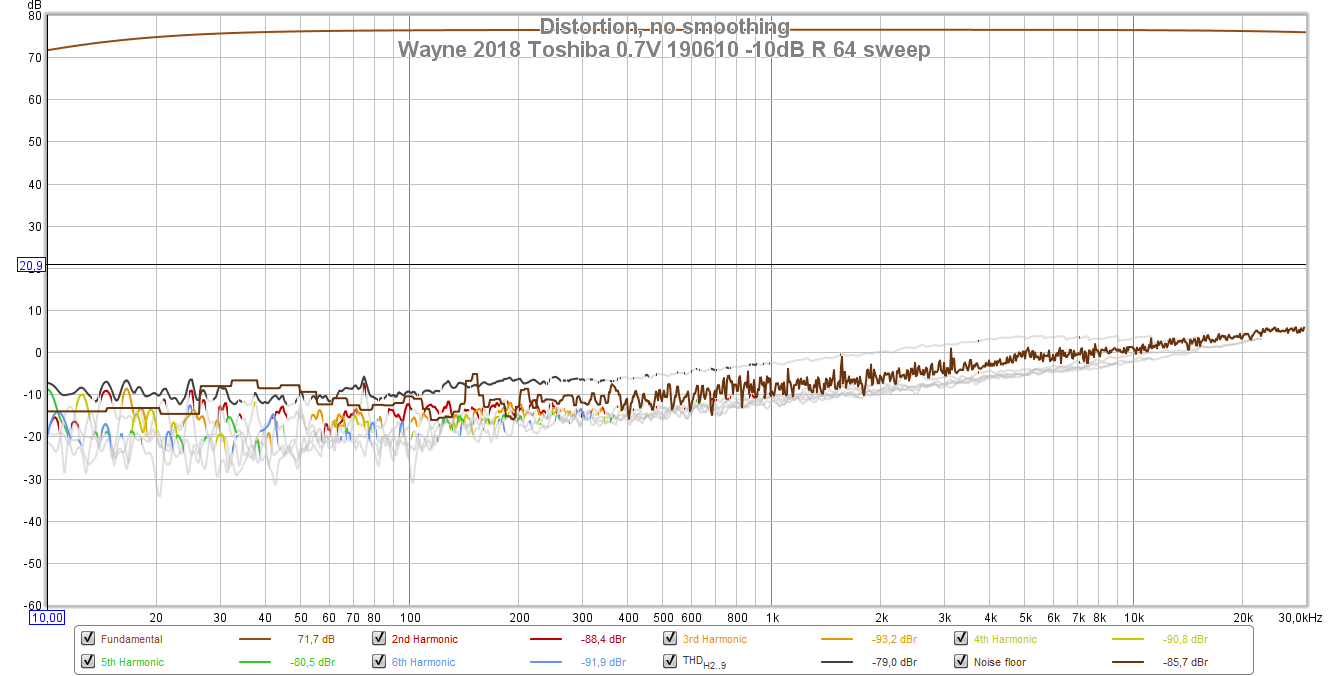
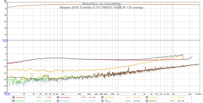
Finally, I got some stepped frequency sweeps to show distortion vs. frequency.
First, at 64 mV RMS ouput voltage:
And the second one at 2.63 V RMS output voltage:
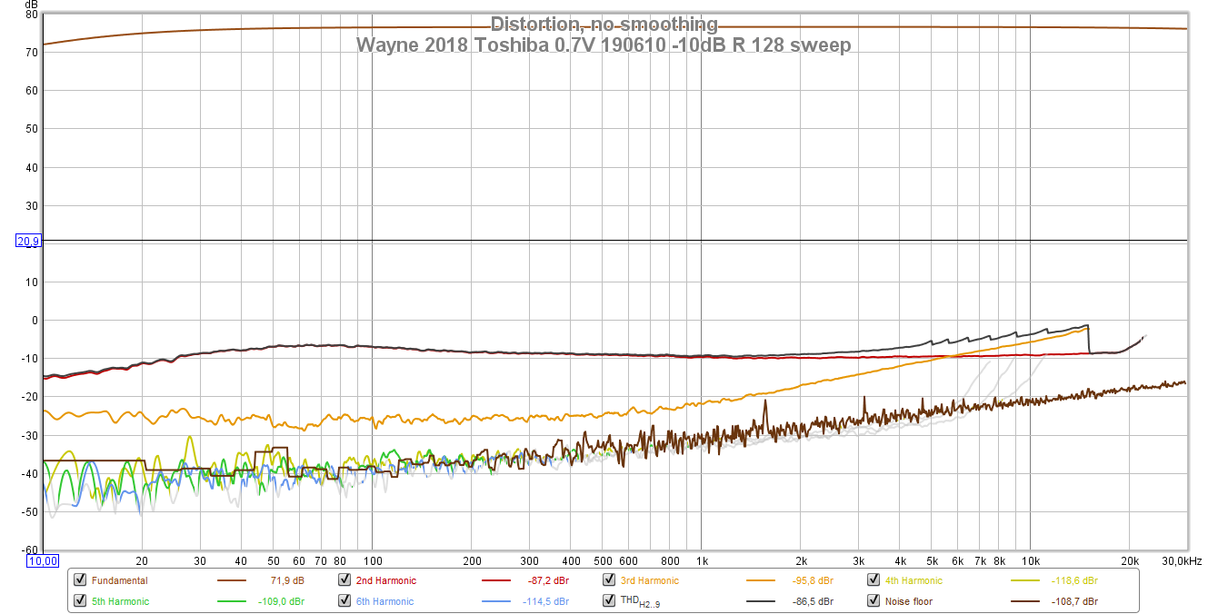
For my build of the linestage in the configuration I had at the time, the lower -3dB point was at around 1.5 Hz (due to the output DC blocking / coupling capacitor), and the upper -3dB point was higher than 2.2 MHz (the upper limit of my frequency generator 😛).
Hope you find this interesting,
best regards,
Claas
Well, in post #837 Wayne showed a measurement of distortion vs. output voltage.
I dug out the pictures from my own measurements, done with a Focusrite 2i2 and REW. My BAF 2018 linestage (see my earlier posts in this thread) was built with Toshiba TTA004B and TTC004B as output transitors, 15R emitter resistors for the outputs, and a WIMA MKP10 1uF cap at the output.
All measurements are with 0.7V RMS input signal, attenuated by the preamp resistive divider circuitry the line stage is built.
So here it goes, 64 mV RMS output:
The next is 390 mV RMS output. Please ignore the hash to the right of the 1kHz fundamental, that's spuriae from the relay-based attenuator's control logic that is feeding through into the signal:
Now, 1.49 V RMS output voltage:
And, 2.63 V RMS output (no attenuation):
Finally, I got some stepped frequency sweeps to show distortion vs. frequency.
First, at 64 mV RMS ouput voltage:
And the second one at 2.63 V RMS output voltage:
For my build of the linestage in the configuration I had at the time, the lower -3dB point was at around 1.5 Hz (due to the output DC blocking / coupling capacitor), and the upper -3dB point was higher than 2.2 MHz (the upper limit of my frequency generator 😛).
Hope you find this interesting,
best regards,
Claas
Attachments
-
 Wayne 2018 Toshiba 0.7V 190610 -4dB R 64.png70.2 KB · Views: 1,136
 -
 Wayne 2018 Toshiba 0.7V 190610 -4dB R 96.png73.8 KB · Views: 1,138
 -
 Wayne 2018 Toshiba 0.7V 190610 -4dB R 120.png73.9 KB · Views: 1,116
 -
 Wayne 2018 Toshiba 0.7V 190610 -4dB R 128.png70.5 KB · Views: 1,125
 -
 Wayne 2018 Toshiba 0.7V 190610 -10dB R 64 sweep.png92.6 KB · Views: 1,121
 -
 Wayne 2018 Toshiba 0.7V 190610 -10dB R 128 sweep.png94.3 KB · Views: 1,116
Thanks for the measurements Chede. I was also using TTA004 and TTC004 outputs during tests presented here. My THD and profiles were similar to your as measured but I had some +/30v rails.
Here was 2Vpp into 52kOhm load with 0.0017% THD and second harmonic dominant signature - nice sounding preamp:
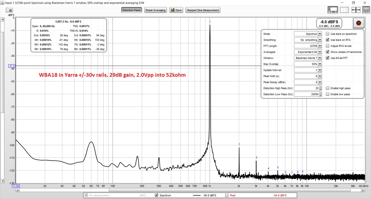
Was your load impedance 64ohm? That's headphone amp terrritory more so than line-level preanmp.
Here was 2Vpp into 52kOhm load with 0.0017% THD and second harmonic dominant signature - nice sounding preamp:
Was your load impedance 64ohm? That's headphone amp terrritory more so than line-level preanmp.
Last edited:
Hi xrk971,
no, load impedance in my case was 100k Ohms. Sorry, had not included all info in my previous thread ... the last number in the naming of my measurements just was the setting of my volume control 😉, which sits before the input to the line stage ... it has a constant 50k input impedance, but it's output impedance (what the line stage sees as input impedance varies from about 1k at low volume settings to about 25k at max. volume setting.
Resulting output voltage of the line stage for a signal input of 0.7V RMS into the volume control is noted before each pic.
Rail voltage in my case is +/- 18V dc.
Best regards, Claas
Listening to it now. Sounds very nice. The cap coupling was key to getting rid of all that DC drift on this circuit.
Not as yet. We are waiting patently for them to come up in the Forum Store. Wayne has very kindly redesigned the board for our easier use and sent the info to DIYaudio Store decision maker/manager. We can not but continue to wait!
[edit:
See that I have been beaten by a minute by our esteemed 6L6]
[edit:
See that I have been beaten by a minute by our esteemed 6L6]
Last edited:
- Home
- Amplifiers
- Pass Labs
- Wayne's BA 2018 linestage