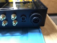
Yesterday, the case arrived that I intend to house Wayne's BA 2018 linestage in:
(image))
That case already comes as a passive preamp, with 128 step relay-based volume control and 4-way input switching, also remote-controlled via a supplied infrared remote:
((image))
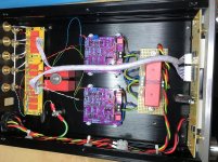
I will use a separate PSU for this preamp. That will be configurable to also serve other future preamps. So, making room for the gain stage boards (relay board will also be moved closer to the back panel):
((image))
PSU build will commence once two more shipments from China have arrived. I also have to order a transformer from Toroidy and a case for the PSU from Modushop. After the Easter break ... 🙂
Follow-on to post #619, and just a quick update of my progress. Have removed the pictures from my quote to save some space. Picture of the board is in #621, and some more info in the posts following that one ...
So, last thing that had happened was that I removed the transformer and the IEC inlet & switch from the passive preamp I bought. Now fitting connectors for the umbilical to the external PSU (+/- 18V or so for the boards, and +12-15V for the relays and control, plus PE) and for connecting a headphone. I chose the connectors so that they fit the existing opening, and I don't have to drill or file so much:
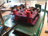
The boards I mounted on the bottom plate using the Adafruit Edge Connector Kit 6L6 mentioned (Mouser):
Pre-assembling the boards together with some rail buffer capacitors, the output caps and a case ground post on the bottom plate:
Preamp wired up with power and signal connections:
The PSU will take a bit more time, though. The case from Modushop is on its way, but Toroidy apparently haven't wound my transfomer yet, and now they have national holidays until next Monday ...
Best regards,
Claas
Attachments


Last edited:

I was asked whether I want to play with a pair of these.
I was not planning to, but did oblige in the end.
The special wish was that I should try this with the TTA004B & TTC004B.
Before doing that, as I normally do, I simulated a few variants for distortion and stability.
All the models were either from manufacturer, or reliable source.
So they should not be too far from reality.
Note that for the open loop simulation, input is at -120dB (1µV).
BTW I hope Wayne would forgive me for messing around with his creation.
The first one to simulate is of course the original circuit.
The results are similar to what was mentioned in Wayne's presentation.
There is not a lot of open loop gain, so about 30dB NFB.
Open loop bandwidth is impressive.
So NFB is constant over the entire audio band.
There is not a lot of phase and gain margin, and it is not unity gain stable.
Patrick
.
Attachments
Then I wanted to know how the "high power" version performs.
Not too surprisingly, distortion goes up even with the same 600R load.
This is most likely due to the much lower hfe of the KSC2690-KSA1220 pair.
Open loop gain drops quite significantly.
But now it is unity gain stable.
So you can even use it as a buffer.
Patrick
.
Not too surprisingly, distortion goes up even with the same 600R load.
This is most likely due to the much lower hfe of the KSC2690-KSA1220 pair.
Open loop gain drops quite significantly.
But now it is unity gain stable.
So you can even use it as a buffer.
Patrick
.
Attachments
But I want to have something that can drive 30 ohm headphones and still have no distortion.
So I used the same approach as the Pioneer Super Liunear, namely Darlington output pair.
Now distortion is very respectable even at 2Vrms into 30R.
I also find that changing R23 from 330R to 1k will improve the phase marginat gain >3.
So feel free to play around in Spice. It is free. 😉
Patriick
.
So I used the same approach as the Pioneer Super Liunear, namely Darlington output pair.
Now distortion is very respectable even at 2Vrms into 30R.
I also find that changing R23 from 330R to 1k will improve the phase marginat gain >3.
So feel free to play around in Spice. It is free. 😉
Patriick
.
Attachments
Of course it would not be complete without a Toshiba-only version.
I know that 2SC2240 / 2SA970 are obsolete.
One can use the SMD versions (2SC3324 / 2SA1312) instead.
But the SMD parts can take only 1/3 of the dissipation.
So they are definitely not suited for anything higher than 15V 3mA.
Or you will have to use multiples in parallel.
Anyway, if simulations are to be trusted, the TOS version has 10x lower distortion.
Which is of course a real surprise.....
Patrick
.
Attachments
Finally, the HPA version using TTA004B / TTC004B as Darlington output.
Not bad at all with -90dB (mainly 2nd) for 1Vrms into 30R.
I could not help wondering how much lower it could be with a complementary front end.
So much for now.
I have too many things on my to-do list.
So it might be months before I can get round to playing with hardware.
But I am sure there are no shortage of bravery here to maybe try one of the above.
Just for fun.
🙂
Patrick
.
Attachments
Finishing up Wayne's line stage.
Thank you Wayne, Jim, and Nelson Pass for your generosity and for making this hobby so much fun.😀


Thank you Wayne, Jim, and Nelson Pass for your generosity and for making this hobby so much fun.😀
Thanks Jim. You helped all of us out here in many ways, especially kitting up Wayne's boards and all the components.🙂
Having a problem that is driving me crazy.
The system is a Wayne's line stage driving an F5TV2 . Normal F5 output bias current set to .360v across .5 Ohm resistors. Turn on line stage F5 bias current goes way up to over .5V across resistors. If I remove ac ground (unplug ground pin in AC plug) from line stage then F5 output bias goes back to normal, .360V across resistors???? I have a signal ground lift bridge rectifier/CL60 in the F5 and had one in the line stage but removed it and connected the power supply ground directly to PE ground and Chassis similar to Jim's in post #179
The system is a Wayne's line stage driving an F5TV2 . Normal F5 output bias current set to .360v across .5 Ohm resistors. Turn on line stage F5 bias current goes way up to over .5V across resistors. If I remove ac ground (unplug ground pin in AC plug) from line stage then F5 output bias goes back to normal, .360V across resistors???? I have a signal ground lift bridge rectifier/CL60 in the F5 and had one in the line stage but removed it and connected the power supply ground directly to PE ground and Chassis similar to Jim's in post #179
Seems like a ground loop between two chassis grounds at the AC plug and the RCA interconnects. What I don't understand is why other line stages do not present the same problem with the F5.

Measurements are on Wayne’s presentation from BAF 2018. Linear Systems
Listening impression- I put it into my system once competed and haven’t replaced it since. (Even having built two other preamps in the time being) I really, really like it.
Listening impression- I put it into my system once competed and haven’t replaced it since. (Even having built two other preamps in the time being) I really, really like it.
Measurements are on Wayne’s presentation from BAF 2018. Linear Systems
Listening impression- I put it into my system once competed and haven’t replaced it since. (Even having built two other preamps in the time being) I really, really like it.
Surprisingly, I find myself in same boat!
Russellc
- Home
- Amplifiers
- Pass Labs
- Wayne's BA 2018 linestage