Check the voltage across R13 and then R14. Should be the same. R14 voltage, up one Vbe and down one Vbe from R13. Start there.
Just zeroed out the offset using P1 & P2... and re measured.
R7 1.69
R38 1.69
R13 1.7
R14 1.75
R31 1.67
R26 1.68
R7 1.69
R38 1.69
R13 1.7
R14 1.75
R31 1.67
R26 1.68
Those values look good so far. You should have a voltage drop across the LED (polarity) unless it is shorted.
and just for giggles
R4 0.84 (second board R37 0.82)
R5 0.82 (second board R35 0.80)
R15 29.4 (second board R30 29.2)
I have 0.15V across one LED and 0.3V across the other
R4 0.84 (second board R37 0.82)
R5 0.82 (second board R35 0.80)
R15 29.4 (second board R30 29.2)
I have 0.15V across one LED and 0.3V across the other
I don't have R31, R26 on my schematic from Waynes's presentation. Do you have a schematic you can post for reference.
There is nothing across R11 and R12 (R32 & R33.. nothing on either board....)
guessing their fried.
guessing their fried.
I have a couple of blue Leds to hand (C503B-BAN-CY0C0461) but they have a different specified forward voltage of 5V. Guessing these wont work as replacements...
will pull the output pair...
will pull the output pair...
I assume there is no way with a simple DVM to test whether the original output TTA004/TTC004 pair are fried?
Assuming the safe option is to just bin them..?
Assuming the safe option is to just bin them..?
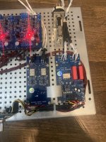
I pulled R11 & R12 as they may have been cooked and Q8 and Q10 so entire last row missing.
remeasured R7 1.7V
1,67V (R38 on other board)
remeasured voltage drop across LEDs at .3 on one and .15 on the other - same as before
remeasured R7 1.7V
1,67V (R38 on other board)
remeasured voltage drop across LEDs at .3 on one and .15 on the other - same as before
Check the LED with your DVM. Remove LED diode, set DVM to diode test and forward bias the LED, it should light up and show a voltage of around 1.7 volts. Reverse biased it should have no reading.
Yes you can test them. Set your DVM to diode test and test the emitter to base junctions just like testing the LED except the junction voltage will be .66 volts when forward biased. Then check the other junction base to collector. Lastly check the emitter to collector to see it's not shorted.I assume there is no way with a simple DVM to test whether the original output TTA004/TTC004 pair are fried?
Assuming the safe option is to just bin them..?
ordered new parts.
LEDs did not come out in a testable condition, so nothing learned (other than to allow parts to stand off the board to enable later cutting of legs if required...)🙄
And apologies I missed the earlier post... about R31 and R26 not being on schematic.
The second board of the stereo pair have different numbers...
R7 (on other board is R38)
R11 (=R32)
R12 (=R33)
R13 (=R31)
R14 (=R26)
Appreciate the help,
thanks,
m
for the betterment of my understanding...
If the output pair are swapped and go fully on, what is the mechanism that kills the LEDs?
If the output pair are swapped and go fully on, what is the mechanism that kills the LEDs?
I think, which could get me in trouble, if you swapped and rotated the pnp and npn transistors you would have a forward biased collector-base junction, thus V+ and V- would be across the LED. Minus the junction voltages. For a little while. Not much resistance to impede the current.

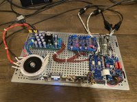
Thought I would share my partially finished Wayne’s build with Academy Audio’s new BIB kit.
Lenny has been VERY helpful explaining what I need and how to hook it up.
I got the optional BOB board so I have fully balanced input and output. He also included a nice mounting bracket to hold the MCU module and the screen.
It works and sounds really nice. I just need to put it in the chassis, add the other 2 xlr inputs, and figure out the best way to add my headphone jack plus a rca inputs/outputs for more versatility.
It sounds really good.
Attachments

- Home
- Amplifiers
- Pass Labs
- Wayne's BA 2018 linestage