Andy, I don't do much measurement but when I do, I use an HP8903. (I'm still sorting out/learning how use a computer setup.)
I know. It probably tells him a lot.Pa especially likes those gigglywigglies you're getting with your HP

example, I am wondering why the sines are sharper on the bottom than the top. Poor matching or implicit for the circuit?
or maybe my bad equipment setup

comparing with the B1K, having much more distortion, sines were cleaner and smoother. But then again, distortion is much lower on the WLS, probably meaning the 334A is struggling more to get a clean signal out of very little voltage, plus noise pickup is probably more of a relevant factor.
repeat your measurements
when you see something odd in output shape, always check is input shape still good
when you see something odd in output shape, always check is input shape still good
Wilco. But the fundamental output shape is in the scope, above the residual waveform. And the fundamental is fine… hmmmrepeat your measurements
when you see something odd in output shape, always check is input shape still good
Even if I really want it to be?residual is never fine looking, you
I guess residual is residual. Just look what happened to James Bond. Far from the fundamental, more like severe IMD

but still, rather fetchy. In fact, my WLS residual kinda resembles his chest hairs.
Attachments


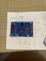
What I have used are visible at posts #3,190 and #3,200hello, just completed Wayne's line stage. Can anybody recommend a pwr supply.I was thinking about the sigma 22 from amb not sure?also a ready to go chassis. I am not very good at cutting holes.
I do not like drilling either but I want to support our fellow HiFi2000 supplier Gianluca. I have never been let down by his service or products 😉

Newbie question. The larger Toshiba devices are rectangular. No curved side to guide my installation. How does one orient them?
Thanks,
Paul
Thanks,
Paul
Both types have markings with their name on the front side of the case, you'll notice when you see them. You can also download the data sheets from the WEB, which give details about the pinout and show a schematic drawing of the case.Newbie question. The larger Toshiba devices are rectangular. No curved side to guide my installation. How does one orient them?
Thanks,
Paul
Always worked for mee too. But only need it from time to time. a tester is probably very nice if building a lot and sourcing parts from different manufacturers.Both types have markings with their name on the front side of the case, you'll notice when you see them. You can also download the data sheets from the WEB, which give details about the pinout and show a schematic drawing of the case.
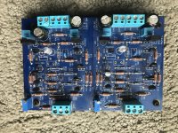
A little help please. I built the kit and a power supply kit. The power supply is providing 18v- and 18v+ beautifully. When I connected the two and powered up the LEDs in the linestage both lit for about 2 seconds and went out. I shut down and dug in. After sorting a couple issues and some re-flow work I installed two new LEDs and fired it up. LEDs were not lit. When I powered off the LEDs lit and then faded out slowly. I inspected everything I could think of and tested every transistor, reflowed a couple more spots and PRESTO ...... still no workie. I have no hair to tear out except on my chest. pics
Attachments
You need R23 & R46, 330 ohm, and C4 & C9, 220 pF caps. Sorry, your using the large output devices, both of my builds use the little ones and use the resistors and caps.
Hello Pmat,
what kind of new LEDs have been installed? They have to be of correct type / value regarding mA-range and
behaviour to bias your outputstage properly. 15 Ohm- bias-resistors are in.
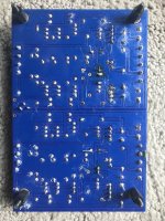
The LEDs have the correct orientation on the pcb. I can see this on the pic.
Are your rail-voltages (+18 V / -18 V) stable?
Only some thoughts.
Cheers
Dirk
what kind of new LEDs have been installed? They have to be of correct type / value regarding mA-range and
behaviour to bias your outputstage properly. 15 Ohm- bias-resistors are in.
The LEDs have the correct orientation on the pcb. I can see this on the pic.
Are your rail-voltages (+18 V / -18 V) stable?
Only some thoughts.
Cheers
Dirk
Sure you didn’t connect power leads to signal input instead of DC input?A little help please. I built the kit and a power supply kit. The power supply is providing 18v- and 18v+ beautifully. When I connected the two and powered up the LEDs in the linestage both lit for about 2 seconds and went out. I shut down and dug in. After sorting a couple issues and some re-flow work I installed two new LEDs and fired it up. LEDs were not lit. When I powered off the LEDs lit and then faded out slowly. I inspected everything I could think of and tested every transistor, reflowed a couple more spots and PRESTO ...... still no workie. I have no hair to tear out except on my chest. pics
your boards are messy, with suspicious joints still. Looks like you have been rushing along. Not a good idea with this circuit.
also: you say you replaced the LED’s. With what LED’s did you replace them? These LED’s are a specific type, and are part of the biasing of the circuit. If you used something else than in the kit, remove immediately and order proper ones.
if LED’s are the correct type, I suggest you;
1: Clean the boards properly with isopropanol and a toothbrush. Rinse several times. Focus especially on the JFETs. They will not work properly with greasy flux residue around them.
2: Confirm correct LED orientation. Since they lit upon shutdown, I suspect you either put your power in where the signal input is supposed to go, or that they are inversely orientated, or that they are the wrong type.
3: Connect DC wires to the correct place, including gnd.
4: Short inputs (gnd to minus, plus to minus).
5: Power on. Do LED’s light up?
6: Focus first on the the right channel. Connect your DMM set to DC volts or millivolts across R1, then R2. Observe voltage drop. It should be approx 0V3 (0,3 volts, or 300mV. Divided by 10R this gives the proper CCS current of approx 30mA. Report your findings here. If CCS is OK and LED’s light properly, it is possible to proceed with further troubleshooting.
Anyways, same drill as always: check all parts are in correct place, and that all active components and caps with polarity are correctly orientated.
Regards,
Andy
The LED’s are of the wrong type. 100% certain. Beat me to it, Dirk, but of course I missed that they are correctly orientatedHello Pmat,
what kind of new LEDs have been installed? They have to be of correct type / value regarding mA-range and
behaviour to bias your outputstage properly. 15 Ohm- bias-resistors are in.
The LEDs have the correct orientation on the pcb. I can see this on the pic.
Are your rail-voltages (+18 V / -18 V) stable?
Only some thoughts.
Cheers
Dirk
You need to snip off all the excessive leads, reflow and clean the board. I see a lot of potential for shorts
- Home
- Amplifiers
- Pass Labs
- Wayne's BA 2018 linestage