With your help I am willing to develop a bill of materials and post it back here for anyone who wants to build your flavor of the preamp. I might be a little slow in getting it done since I am in the finishing stages of building an F6. My interest is that I may want to use this preamp one day with the F6. What are your thoughts about providing for one or two more inputs to the preamp for the sake of flexibility? Probably a space problem I guess, Any other drawbacks?
Count on me. I'd love to give back even a small fraction of what I have gained so far on this forum. 🤓
I think there is space for one more pair of RCA on the back panel and you can have a simple switch in between to select source 1 or 2. If you can live with the switch on the back panel and only 2 sources, this is it. And I may add this exact feature at some point down the road.
However, I like to keep the wiring as minimal as possible. So my preamps (so far) have a single input. I use an external switch box to select my source. In this way the switch box stays there all the time and when I want to use a different preamp I only need to unplug-and-plug two pairs of RCA.
I have to say that my choice to have "compact" builds is also because I have limited space. Hence, I prefer to have a shorter case that facilitate the arrangement of external cables behind the pre in my rack instead of a deeper case with the internal space for a properly wired rotary switch.
Interesting. Thanks very much for sharing.william2001
I've built three BA2018s and had forgotten that the one with a SRPS was built with a dual-mono, split-able BA board I got from forum member IckyB. Also, the SRPS board is a layout I did myself, taken from schematic V2.3 with an added on-board transformer, rectifier/filtering circuit and power LED connection. So the attached photo may not be much help. It's also possibly the densest chassis build I have done.
For what it is worth, the SRPS ICs (just barely visible at the far left) are AD825 and there is a 0.01uF bypass cap connected between the SRPS ground and chassis ground. Ref voltage is 6.9V and R15/25 (R6/13 on V2.3 schematic) is 1.5K ohms, providing around +/-18V at the regulator outputs.
The IckyB board (not split into 2 pcs) has power connections on the outside edges and also in the middle where the two circuits are divided by the score line. I connected DC power to both channel edges on separate home runs and the sense wires to the board middle and jumpered across the split line. All the power and sense home runs are twisted pairs.
Schematic and parts list for my V1.0 SRPS is attached for reference. The IckyB boards follow Wayne's schematic but not his layout.
I'm assembling a similar build except I'm using the standard diy store boards and I'm planning to have separate power for each channel.
I was wondering:
How did you calculate/choose the values for the CRCRC filter before the regulator? Was it to pad down the rectified voltage? I had thought to use a common mode choke a la Galo but the test mock up seems to run "hot".
Also, I was wondering how you chose the point in the circuit to connect the sense? My initial impression would be that it made "sense" to connect it mid-way along the +/- traces on the board but most implementations I've seen have just connected it to the same connection as the voltage itself. Did you try different locations?
Thanks.
Hello members,
I am also playing around with Waynes Line Stage.
I made two builds of the original boards from the diyAudiostore. I used bigger output BJTs (Toshiba TTA/TTC004A). Why? Because it is also an excellent Headphonamp...
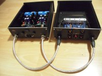
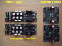
I 've built mine in three cases:
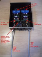
-PSU (each channel has its own PSU - dual mono)
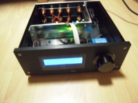
-preamp
- one case with inputs switching and volume control.
I did this to have a modular system. I can use the 'PAC' (Pre Amp Controller) for other preamp projects.
At the moment I make my own PSU boards. CRCRC-filter with following regulator. I used AnalogDevices
LT1085/LT1033 (or LM317/LM337). Via potentiometer I can adjust +-V DC out from PSU in a very wide range.
I want to play with different transistors in Waynes Line Stage. Not that I think I can do better than Wayne!
For sure not. But I am curious.
I made one board with the Onsemi Jfets '2SK3557' (instead of the Toshiba 2SK209). But the onsemis have a much lower Vmax than the Toshibas. Instead of the fairchild KSA992/KSC1845 I used ZTX851/951. This project is still in progress... Don't ask me how it sounds.
So, have fun with Waynes Line Stage - it is an excellent preamp and headphoneamp!
Cheers
Dirk 😉
I am also playing around with Waynes Line Stage.
I made two builds of the original boards from the diyAudiostore. I used bigger output BJTs (Toshiba TTA/TTC004A). Why? Because it is also an excellent Headphonamp...
I 've built mine in three cases:
-PSU (each channel has its own PSU - dual mono)
-preamp
- one case with inputs switching and volume control.
I did this to have a modular system. I can use the 'PAC' (Pre Amp Controller) for other preamp projects.
At the moment I make my own PSU boards. CRCRC-filter with following regulator. I used AnalogDevices
LT1085/LT1033 (or LM317/LM337). Via potentiometer I can adjust +-V DC out from PSU in a very wide range.
I want to play with different transistors in Waynes Line Stage. Not that I think I can do better than Wayne!
For sure not. But I am curious.
I made one board with the Onsemi Jfets '2SK3557' (instead of the Toshiba 2SK209). But the onsemis have a much lower Vmax than the Toshibas. Instead of the fairchild KSA992/KSC1845 I used ZTX851/951. This project is still in progress... Don't ask me how it sounds.
So, have fun with Waynes Line Stage - it is an excellent preamp and headphoneamp!
Cheers
Dirk 😉
Attachments

Hello myleftear,
I don't want to make anybody jealous.
Waynes Line Stage is a fantastic preamp as it is. Everybody of us 'greedy boyz' can build one.
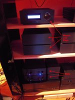
My first try was built on the wooden board with a simple PSU, the official board from the store
and an ALPS-pot at the input. No input switcher.
And then I listened and was surprised...
Have a nice weekend
Dirk 😉
I don't want to make anybody jealous.
Waynes Line Stage is a fantastic preamp as it is. Everybody of us 'greedy boyz' can build one.
My first try was built on the wooden board with a simple PSU, the official board from the store
and an ALPS-pot at the input. No input switcher.
And then I listened and was surprised...
Have a nice weekend
Dirk 😉
Yes! I didn‘t mean it in a negative way, more like a hidden compliment, like, woah, that’s soo cool!

Hey Dirk
Nice idea and realization.
I'm channeling John Curl a little too -- dual mono construction throughout -- but I'm intending on locating the regulation close to the signal boards.
How did you come up with the CRCRC filter section? Was taming the voltage a part of the intent?
Nice idea and realization.
I'm channeling John Curl a little too -- dual mono construction throughout -- but I'm intending on locating the regulation close to the signal boards.
How did you come up with the CRCRC filter section? Was taming the voltage a part of the intent?
Hello mhenschel,
locating the regulator close to the preamp-pcb is a good idea. Sometimes you have to make
compromises...
Using a CRCRC-filter is for me always combined with testing. I often solder the Rs that way in, that they are
easily desolderable. On the other hand we have the rule of thumb, that the AC sec. voltage at your transformer multiplied with a factor of 1.3 to 1.4 will be your DC voltage after the rectification and CRCRC-filter. A nice tool is Duncan's PSU Designer 2.
https://www.duncanamps.com/psud2/
If I use a transformer with 2 x 24 V AC sec. I assume that after the rectifier and CRCRC-filter I will be anywhere around 31 V DC to 34 V DC. You can adjust this with different R-values = burn some voltage. And the combination of C-values and R-values is also important for filter-characteristics. In Germany we have
230 V AC / 50 Hz AC mains voltage. So it would be nice to filter the 50 Hz-hum and its multiples (100 Hz,...)
as good as possible away.
I prefer to go pretty high - or lets say minimum 4-5V over my target-voltage and then I regulate down.
For me the limit is the Vmax at input of the regulators (or deltaVmax for the regulators). And I also look
at the heat dissipation. It makes no sense if your target-voltage would be 12 V DC and you have 34V after the CRCRC-filter and you burn 22V away. Only some thoughts.
Cheers
Dirk 🙂
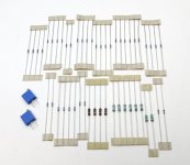
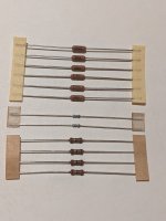
The most recent batch of parts kits contains the very nice, but very small, premium, European-made, Vishay MBA series resistors. Albeit a small package, these are ceramic bodied and 0.4W (almost 1/2W) max dissipation, and we are using them in lieu of the more common 1/4W (0.25W).
The body size is comparable to an old 1/10W (0.1W) or maybe even smaller. Some people may erroneously think they are 1/10w resistors and we are being cheap, nothing could be further from the truth. The parts available in the current electronics reality require trying some neat and nifty new things. They work perfectly and sound fantastic. Will the (very easy to read, which is why I prefer them,) Dale RN-series ever be available again from distributorship in the quantities we need at a price than isn't fully ridiculous? I'm not holding my breath, and published lead times are increasing. This is true of a LOT of various parts, the supply chain is genuinely messed up.
The “large” resistors in the photos are normal-sized 1/4W (although the brown ones are 0.4W…)
Please note that the PCB shown stuffed is setup for using the “big” output transistors, where R11,12, 32, 33 are 15ohm, and R23, 46 are omitted.
Also worth note, in this most recent 'big' transistors are the fantastic Toshiba TTA004B/TTC004B. Genuine, in-production Toshiba through hole transistors. Sometimes there really is a silver lining. 🙂
Attachments
Last edited:
Is there any advantage of dale RN vs dale CMF or other dale types? I looked into it a bit and can't find anything that explains any reason to splurge on the RNs.
They are VERY easy to read in photographs, and have the value written on them instead of the color stripe code, so generally they are a lot more user friendly for hobbyists.
They have gotten extremely expensive, and difficult to obtain, so alternatives are being used.
They have gotten extremely expensive, and difficult to obtain, so alternatives are being used.
Yes, I like the Dale resistors specifically due to them having the value printed on the actual part. I also think they are very consistent. The CMF series are quite a bit cheaper and still have the value printed. I generally purchase the 1/2w variety.
I do see that the RNs tend to be larger. Maybe the RN series is just overbuilt vs the CMF.
I do see that the RNs tend to be larger. Maybe the RN series is just overbuilt vs the CMF.
The RN’s are milspecced so they are a bit larger and can dissipate a bit more than specified.Yes, I like the Dale resistors specifically due to them having the value printed on the actual part. I also think they are very consistent. The CMF series are quite a bit cheaper and still have the value printed. I generally purchase the 1/2w variety.
I do see that the RNs tend to be larger. Maybe the RN series is just overbuilt vs the CMF.
Another useless long post of mine: Jim doesn't really need any extra comment or back up in his direction, but I couldn't resist applauding this clever resistor choice.
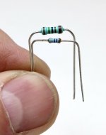
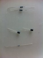
As things are, beginning of 2019 I decided to evaluate several volume pots and to proceed I needed what I considered a perfect benchmark: a high quality pure/simple harwired discrete voltage divider (so only one attenuation value). This was found to 'sound' best and perfect enough to my ears, so that in fact I still use it as a reference. It is built around the excellent small Vishay MBA resistors 6L6/Jim just recommanded and these proved to be not only inexpensive but also simply... excellent. Don't be put off by the long legs (never a good thing) in the attached pix: in fact the resistors are indeed small and this divider being used in various test rigs I need some minimal length to attach in in various ways, of course often as close as possible to the entry and exit resistor not using all the legs length.
TBH, I am not really in 'resistor sound' and AFAIC once you chose a high quality metal resistor with very low tolerance and drift / ppm "you are probably good". Not saying that resistors can't sound differently, but saying that from a certain level on they IMHO ought to be as neutral as possible - some other resistors can be more pleasant but being in fact IMHO coloured and hence not what I personaly expect from a resistor (and that's just me!).
So for my expectations the best resistor is not the "best sounding one" (only kidding here of course), but the one that in fact doesn't have any sonic signature at all, the one that disapears. I used the recommended Vishay MBA to EXCELLENT effect 3 years ago and never looked back since: I still use my provisory reference voltage divider and have yet to come across a pot that can beat it. This pure resistor network simply 'sounds' excellent over all frequencies, from the deepest tones to the highest pitches, and flooooows so well with music.
Excellent VFM and excellent choice again by the store - please, please, please don't be put off by their small size and "non expensive appearance" (I was 'surprised' when I first unpacked them): only the result counts. Oh, and they aren't that difficult to solder nor will you lose them that easily, despite being indeed small 🙂
Have a nice Sunday
Claude
Attachments
Last edited:
I do like them just not in electronics.long legs (never a good thing)
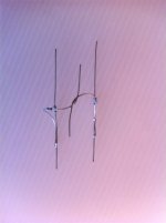
I know frequencies in audio are terribly low but still I had to laugh a bit seeing the example build from the diyaudio store.
The army of TO-92´s seems to have legs of >1cm by the looks of it.
Wayne's Burning Amp 2018 Linestage (diyaudio shop)
I would think that you don't want your resistors to be able to be too tough. In certain situations, the component down the road will take the hit. temco's are generally available at 25ppm/c-100ppm/c but even then, most resistors on a board don't end up being too high over ambient temp so I wonder of that has a noticeable effect. Maybe a resistor that isn't supposed to get hot should have a high tempco so that if too much power goes through it, it will get hot and resist more. Then there is the question, is there an audible difference between the CMF and the RN's?The RN’s are milspecced so they are a bit larger and can dissipate a bit more than specified.
My knowledge is pretty limited on resistor quality and I may have hijacked this thread enough with my question. Off to google I go. Thanks everyone!
From the CMF datasheet ( https://www.vishay.com/docs/31018/cmfind.pdf ):
"Vishay Dale Model CMF is also available as Military Qualified Styles RN and RL. See Vishay Dale’s CMF (Military RN and RL) datasheet (www.vishay.com/doc?31027) for the MIL-SPEC ratings / attributes. (Except for marking, the Industrial and Military versions are exactly the same)." (emphasis added)
Note that doesn't mean every CMF has an equivalent RN (for example, CMFs are available in lead free versions)
- Home
- Amplifiers
- Pass Labs
- Wayne's BA 2018 linestage