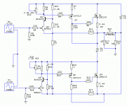
separate B+ supply line just for the VAS stages , but that separate B+ line can be derived from OPS B+/B+`lines, via two resistors and one smoothing electrolytic capacitor connected to ground ,it is somethig like this :
Good idee but why not the input ?
x
by inserting positive fbck(bootstrap) on input JFET`s drains you got max. gain with minimum thd , I think that if you supply input JFET stages from separate B+ line than cascode can help very much perfomance wise , but maybe bootstrapped cascode input stage is even better performer ?
by inserting positive fbck(bootstrap) on input JFET`s drains you got max. gain with minimum thd , I think that if you supply input JFET stages from separate B+ line than cascode can help very much perfomance wise , but maybe bootstrapped cascode input stage is even better performer ?
I am not sure, it depends on the supply voltage and the cascoding transistor, which will have the same current. A high supply voltage restricts the biasing of output stage in particular.
where can a found this article ?
The outputs are of course darlingtons.
Attachments

for the moment the best results are here:
Jfet with differential feedback
jfet_circlotron_1.1A.asc
http://circlotron.audio/data/simulation/img/jfet_circlotron_1.1A.png
http://circlotron.audio/data/simulation/img/jfet_circlotron_fft_1.1A.png
bjt with differential feedback
bjt_circlotron_1.1A.asc
http://circlotron.audio/data/simulation/img/bjt_circlotron_1.1A.png
http://circlotron.audio/data/simulation/img/bjt_circlotron_fft_1.1A.png
Last edited:
I just found this :
Lateral MOSFETs SuSy circlotron - Page 4 - Solid State - diyAudio.rs
Juma already made the same differential feedback with Jfet on a circlotron
Banat, you are also on this forum 😛
Lateral MOSFETs SuSy circlotron - Page 4 - Solid State - diyAudio.rs
Juma already made the same differential feedback with Jfet on a circlotron
Banat, you are also on this forum 😛
Attachments
Last edited:
What would you like to achieve?
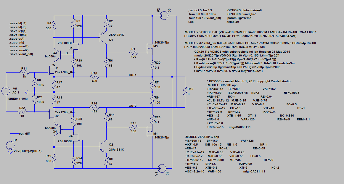
The main purpose of the cascode is to establish a low drain-source voltage, while the voltage amplification is being carried out by a common-base amplifier. The thermal situation of Q3, Q4 can be worrisome. I would connect R19 and R25 to ground.
I am having difficulty suggesting appropriate bias currents at 35 V supply voltage.
X
I like the results , THD spectrum is so incredible clean ,
few question ,
- what is the OPS- IQ ( bias current) ?
- it is possible to make sim of 19Khz+20Khz at full output power blast ?
-------------------------------------------------------------------
for long time I don`t visit that site anymore .
n101n, I do not question the cascode,
I just did not have time to put it in the diagram with differential feedback
on the other hand I think we must use a 20v regulated power supply for input and vas
I just did not have time to put it in the diagram with differential feedback
on the other hand I think we must use a 20v regulated power supply for input and vas
Last edited:
banat,
the output bias is 400mA
ok, I'm doing a simulation at 28V 20Khz and 19 if you want , but why 19khz ?
at full power the THD increases a lot that's why I was asking for help
the output bias is 400mA
ok, I'm doing a simulation at 28V 20Khz and 19 if you want , but why 19khz ?
at full power the THD increases a lot that's why I was asking for help
first of all, should we use an input filter?
I already use the same filter as VSSA for bjt input, but not on the jfet
I already use the same filter as VSSA for bjt input, but not on the jfet
yes I just created the hosting, for now I use it only to share circlotron images and simulatons, but there will be web a site later
x
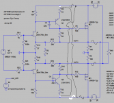
you can also check this variant for connecting VAS emiters on oposite B+(AC) side ( VAS full bootstrap) , as is basically done by Juma`s circlotron amp , but than maybe you will need to change the values of some resistors to get best amp performance .
edit , in this variant you can also try to connect R6/R14 on the ground line , not as is shown on the output lines .
Attachments
Last edited:
- Status
- Not open for further replies.
- Home
- Amplifiers
- Solid State
- VSSA Circlotron