I just found the scheme of Yamaha AS2100 and it seems that this is the same topology as this one but with Jfet input.
http://www.diyaudio.com/forums/solid-state/202701-simple-circlotron-power-mosfets.html
So I could start with a SYMASYM Jfet input to made a Circlotron with balanced current feedback
Yamaha A-S2100 Manual - Stereo Integrated Amplifier - HiFi Engine
http://www.diyaudio.com/forums/solid-state/202701-simple-circlotron-power-mosfets.html
So I could start with a SYMASYM Jfet input to made a Circlotron with balanced current feedback
An externally hosted image should be here but it was not working when we last tested it.
Yamaha A-S2100 Manual - Stereo Integrated Amplifier - HiFi Engine

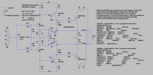
0.001% 10khz 1W 8ohm (4V)
0.02% 10khz 120W 4ohm (31V)

https://sites.google.com/site/solidcirclotron/OPAtriple.asc
0.02% 10khz 120W 4ohm (31V)
https://sites.google.com/site/solidcirclotron/OPAtriple.asc
Hi,
Interesting designs although I was thinking of something more simple.....what do you think of this circuit ...will work ?
Interesting designs although I was thinking of something more simple.....what do you think of this circuit ...will work ?
Hi,
I think there are too many capacitors
If you want a simple schematic with only two stage you could made a mode of this with 2SK1058 : http://www.diyaudio.com/forums/solid-state/270239-i-call-infinitron.html
I will try to sim
I think there are too many capacitors
If you want a simple schematic with only two stage you could made a mode of this with 2SK1058 : http://www.diyaudio.com/forums/solid-state/270239-i-call-infinitron.html
I will try to sim
Last edited:
What do you think about using LME39830 ?
An externally hosted image should be here but it was not working when we last tested it.
An externally hosted image should be here but it was not working when we last tested it.
Hi,
I think there are too many capacitors
If you want a simple schematic with only two stage you could made a mode of this with 2SK1058 : http://www.diyaudio.com/forums/solid-state/270239-i-call-infinitron.html
I will try to sim
Hi UltimateX86 !
Thank you for your response! Yes you are right, too many capacitors in the signal path. The Infinitron circuit looks nice and quite simple. I checked the LME49830 datasheet and apparently is an excellent device for building neat and simple amplifiers. I did a search on the Net and found a lot of amplifiers modules using this remarkable chip. They are Chinese of course. What do you think of these Chinese amplifiers ?
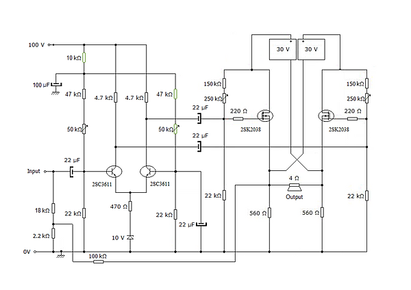
It's basically the circuit UltimateX86 first presented, but with differential feedback applied as described in post #5. There is one other difference, which is that the output stage uses two HEXFETs biased as shown in the Thorens TEM3200 conceptual schematic that you see out on the web.
I first saw this bias arrangement in a BJT circlotron design that appeared in No.8 1984 of RadioHobby, a Russian magazine. It was essentially a lower-power version of the Sumo Nine, with the important difference that the bias current is regulated by a constant current source rather than resistors. This allows for the possibility of temperature compensation, and with that, for the use of either BJTs or high-gm MOSFETs as output devices.
However, this arrangement is not so good for use with lateral MOSFETs in the output, because it limits their drive voltage to twice the bias voltage, which is not nearly enough for full output current. It would probably work well with power JFETs, though.
Hello,
No.8 1984 of RadioHobby, a Russian magazine
where can a found this article ?
thanks
We are nearly there, except two source resistors going to ground in the place of R3.
Complications: JFETs should be operated at low drain-source voltage. You would need four matched pieces of 2SK170BL, a bipolar cascode and two extra resistors.
The 2SK170BL and 2SA1381 are fine.
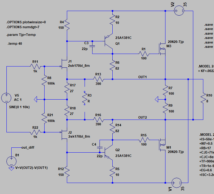
It is possible to keep differential feedback ?
It is looking good, including the feedback arrangement. All JFETs benefit from cascoding. 8 mA current will be far too much.
The references introduced greatly support operational stability. In addition, unbalanced input would be a better option, reducing the value of R8 and R21.
R3 is not needed. I would increase the value of R2 and R5 to something like 100 ohm. The compensation capacitors will probably be unnecessary. What about a carbon resistor on the source electrode of the MOSFETs?
X
did you consider AC conditions on J1/J2 drains and Q1/Q2 emiters ?
no i just saw that it worked by following n101n's instructions and extrapolating other schematics
you think there is a problem somewhere?
do you think that a dedicated power supply is needed ?
Last edited:
It is looking good, including the feedback arrangement. All JFETs benefit from cascoding. 8 mA current will be far too much.
The references introduced greatly support operational stability. In addition, unbalanced input would be a better option, reducing the value of R8 and R21.
R3 is not needed. I would increase the value of R2 and R5 to something like 100 ohm. The compensation capacitors will probably be unnecessary. What about a carbon resistor on the source electrode of the MOSFETs?
8mA is the Idss, I use 5.3mA.
what voltage to apply to the cascode?
unbal input ? I have balanced DAC/preamp and LL1690 especially for the input circlotron 🙁
why increase R2 and R5 ? thermal stability ?
Usually the lateral MOSFET do not need it, especially that there will be no paralleling
Last edited:
X
just for input JFET pair is not the problem since in that configuration their drains are 100% bootstraped , but than care must be taken that max. Vds to be not exceded ,
on the other hand both VAS stage virtually stays beetwen generated AC of balanced output lines , with colectors 100% boostraped(OK), but in the same time with emiters which floats on 100% inverted AC lines(bad).

why increase R2 and R5 ? thermal stability ?
Usually the lateral MOSFET do not need it, especially that there will be no paralleling
To stabilize the base-emitter and gate-source junction, lowering distortion.
unbal input ? I have balanced DAC/preamp and LL1690 especially for the input circlotron
I see. OK.
5.3mA is still too much to me.
Could you implement the cascodes?
- Status
- Not open for further replies.
- Home
- Amplifiers
- Solid State
- VSSA Circlotron