Exactly. Phase of near field cone response will be matched with phase of far field on-axis response in Merger tool by adjusting Delay of LF sum (including baffle effect response) so it does not matter whether near field responses are very close to minimum phase or not. Only thing which matters is that all near field measurements (cones and ports/passives) have the same timing = ca. same distance from mic to mouth of DUT, and same Reference time while converting near field measurements from IR to FR.For nearfield response processing, these small adjustments to reference time aren't very important, but may make some small change to the merge process if you are including port response for example, which is the only reason I can see for this instruction. I generally just hit the "near" button and save.

Hi.
I apologize for asking questions that have probably already been asked many times already. I'm new with VituixCAD and there are a couple of things that i can't figure out. I would greatly appreciate it if someone could help me. I HAVE looked in the manual and I've done my searches, but unfortunately I'm stuck.
Anyway..... I'm building a two-way speaker and I'm trying to simulate the speaker's behavior with Vituixcad. The problem is that I'm not sure how to specify the placement of the individual speaker elements on the baffle.
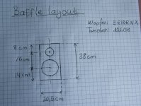
All frequency measurements are made 1m in front of the baffle, at the height of the center points of the speaker elements. On my baffle (20.5 cm x 38 cm) both elements are centrally located. The center point of the woofer (SEAS ER18RNX) is 16 cm below the center point of the tweeter (Scan Speak d2608) (image attached below).
I assume that the acoustic center of the tweeter is in the same plane as the baffle, and that the acoustic center of the woofer is 22mm behind the baffle. In the 'Driver Layout' window I have set (x,y,z)= (0,0,0) for the tweeter and (0,160,22) for the woffer. Is this correct?
Also - At what point in space, (x,y,z), can I assume that Vituixcad does the frequency measurement? Is this something that the user can decide for himself and if so, how?
Thanks in advance for helping a newbie.
I apologize for asking questions that have probably already been asked many times already. I'm new with VituixCAD and there are a couple of things that i can't figure out. I would greatly appreciate it if someone could help me. I HAVE looked in the manual and I've done my searches, but unfortunately I'm stuck.
Anyway..... I'm building a two-way speaker and I'm trying to simulate the speaker's behavior with Vituixcad. The problem is that I'm not sure how to specify the placement of the individual speaker elements on the baffle.
All frequency measurements are made 1m in front of the baffle, at the height of the center points of the speaker elements. On my baffle (20.5 cm x 38 cm) both elements are centrally located. The center point of the woofer (SEAS ER18RNX) is 16 cm below the center point of the tweeter (Scan Speak d2608) (image attached below).
I assume that the acoustic center of the tweeter is in the same plane as the baffle, and that the acoustic center of the woofer is 22mm behind the baffle. In the 'Driver Layout' window I have set (x,y,z)= (0,0,0) for the tweeter and (0,160,22) for the woffer. Is this correct?
Also - At what point in space, (x,y,z), can I assume that Vituixcad does the frequency measurement? Is this something that the user can decide for himself and if so, how?
Thanks in advance for helping a newbie.
Attachments
Member
Joined 2003
Hi Oidua,
If you followed the measurement guide for VituixCAD, you will have measured your drivers using dual channel, or at least semi-dual measurement. This means that the acoustic delay between drivers is inherently captured in your measurement data, provided the distance from mic to baffle remains constant and the window start reference time remains constant when processing the measurements. For this reason, there is no need to make any assumptions of acoustic centre, and the driver coordinates entered into the crossover should be physical offsets only.
You will find in the options a setting for listening distance. This is the distance used for simulation, recommended to keep at 2m+. Coordinates are entered relative to 0,0,0, so 2m listening distance places the simulation at (0,0,-2000). Most people will use the tweeter as the listening height, so the tweeter is entered as 0,0,0 and other drivers coordinates are entered relative to the tweeter. However, some may want to use the midrange as listening height or some point inbetween midrange and tweeter, the choice is at your discretion. You’ll find with your small bookshelf that at 2m distance it won’t change the result much if you use tweeter axis or woofer axis as the listening axis since the relative difference in driver distance and angle will be small.
In your case, using the tweeter as the design axis, the tweeter is (0,0,0) and the woofer is (0,-160,0).
Thanks a lot DcibeL, that's exactly what I needed to know.Hi Oidua,
If you followed the measurement guide for VituixCAD, you will have measured your drivers using dual channel, or at least semi-dual measurement. This means that the acoustic delay between drivers is inherently captured in your measurement data, provided the distance from mic to baffle remains constant and the window start reference time remains constant when processing the measurements. For this reason, there is no need to make any assumptions of acoustic centre, and the driver coordinates entered into the crossover should be physical offsets only.
You will find in the options a setting for listening distance. This is the distance used for simulation, recommended to keep at 2m+. Coordinates are entered relative to 0,0,0, so 2m listening distance places the simulation at (0,0,-2000). Most people will use the tweeter as the listening height, so the tweeter is entered as 0,0,0 and other drivers coordinates are entered relative to the tweeter. However, some may want to use the midrange as listening height or some point inbetween midrange and tweeter, the choice is at your discretion. You’ll find with your small bookshelf that at 2m distance it won’t change the result much if you use tweeter axis or woofer axis as the listening axis since the relative difference in driver distance and angle will be small.
In your case, using the tweeter as the design axis, the tweeter is (0,0,0) and the woofer is (0,-160,0).
I thought it was a bit strange that the coordinates of the woofer would be (0, 160, 0), but in the 'Driver layout' window, it seems that this places the woofer below the tweeter? I might have to take a look at that again.
Anyway - thank you for your help.
Member
Joined 2003
Driver layout window is mostly useless except for arranging arrays, in any case the sign convention for y axis follows common sense where up is positive.
Hi there! Can someone maybe help understand what I am doing wrong when I get a consistent difference in SPL of 9 dB between Arta and Vituixcad when using the IR Converter tool?
I'm using Arta for the Impulse Response measurements in Dual Channel mode. My mic. is calibrated (both frequency response as SPL) and in Arta I measure at 96 KHz SR with 256k sequence length and at -12 dB (which corresponds to 2,00V in my case). Sound pressure units in Arta are set at 20 uPa/2,83V.
Please note that I tried measuring at -9dB as well (so exactly 2,83V) but that does not solve anything.
Off course I can scale the levels in Vituixcad in the drivers menu (or when converting from IR) by 9 dB but I would like to understand what's going on. Besides that I am not a big fan of manual corrections in a workflow as it tends to lead to (human) error.
Last edited:
Hi HighTower. I have exactly the same issue but I couldn't resolve the problem. Always scale results by +9.1dB in IR Converter Tool 🙂... I get a consistent difference in SPL of 9 dB between Arta and Vituixcad when using the IR Converter tool...
^ ^^What do you see in Scale type list box when frequency responses are loaded and first selected?

Member
Joined 2003
The use of pascal or volts for the PIR output in ARTA is dependent on the selection of "microphone used" in the ARTA audio devices setup. I just did a quick test with ARTA and VituixCAD, with "mic enabled" and sound pressure units is ARTA set to "dB re 20 uPa/V", the SPL result is the same. The error appears to be in your selection of SPL referencing 20uPA/2.83V in ARTA. A scaling difference of 2.83V/V = 9.0357 dB.
20 uPa/2.83V unit is correct option to display frequency response in ARTA. I have mic calibrated as described in ARTA manual and verified with external sound level meter
Member
Joined 2003
^^What 2.83 V? Section "1.5 Calibration and Frequency Response Compensation" does not contain anything about "2.83". PIR files know nothing about voltage sensitivity i.e. voltage in driver terminals during measurement.
PIR files contain samples of impulse response as voltage values, and common scaling factor called "devicesens". Scaling factor is V/V for voltage measurements, and V/Pa for SPL measurements with microphone which require checking of "Microphone used on" before measurement.
See section "4.6.1 PIR file format" in user manual:
VituixCAD divides each sample value by devicesens value, and final dBSPL value is 20log10(p/20uPa) i.e. pressure in dB compared to 0 dBSPL. So you should set up ARTA so that VituixCAD gives the same pressure with SPL calibrator - if that is really important.float devicesens; // V/V (for voltage measurement), V/Pa ( for mic input)
It's exactly what I'm doing.Enter scaling factor of 9.0357dB if you want the units to match.
Yes. But I'm using 2.83V because this option gives me accurate SPL results on chart. Maybe I have entered incorrect value of "Preamp. gain" during microphone calibration, but I had to enter this value to mach catalogue mic sensitivity value 14 mV given by microphone producer. I've found it by asking and maybe it was wrong? I'll check other "Preamp. gain" values if it gives me proper SPL values with "db re 20 uPa/V" chart units in ARTA.^^What 2.83 V? Section "1.5 Calibration and Frequency Response Compensation" does not contain anything about "2.83".
^^What 2.83 V? Section "1.5 Calibration and Frequency Response Compensation" does not contain anything about "2.83". PIR files know nothing about voltage sensitivity i.e. voltage in driver terminals during measurement.
PIR files contain samples of impulse response as voltage values, and common scaling factor called "devicesens". Scaling factor is V/V for voltage measurements, and V/Pa for SPL measurements with microphone which require checking of "Microphone used on" before measurement.
See section "4.6.1 PIR file format" in user manual:
VituixCAD divides each sample value by devicesens value, and final dBSPL value is 20log10(p/20uPa) i.e. pressure in dB compared to 0 dBSPL. So you should set up ARTA so that VituixCAD gives the same pressure with SPL calibrator - if that is really important.
Thanks for your fast reply Mr. Saunisto. I hate to be the one to ask the dumb questions but can you tell me which binary code is being used in Arta PIR files? When I decode the files using obvious binary formats then all I get is rubish. I would just like to understand what is in the files and try and find out why we have a consistent 9 dB difference, if we are doing something wrong then we can correct it. The mic is Class 1 calibrated so it must be something else. Besides that Arta is showing correct SPL @ 2,83V.
Catalogue mic sensitivity is irrelevant. Preamp. gain is not included in PIR file so it must be 1. Gain of soundcard input should be included in mic sensitivity in order to deliver correct sensitivity value to PIR file. This happens automatically when sensitivity is measured with microphone calibrator and 'Estimate Mic. Sensitivity' button, and accepted with Accept button.Yes. But I'm using 2.83V because this option gives me accurate SPL results on chart. Maybe I have entered incorrect value of "Preamp. gain" during microphone calibration, but I had to enter this value to mach catalogue mic sensitivity value 14 mV given by microphone producer. I've found it by asking and maybe it was wrong? I'll check other "Preamp. gain" values if it gives me proper SPL values with "db re 20 uPa/V" chart units in ARTA.
Main purpose of frequency response measurement is not to show dB/2.83V/1m of the driver or speaker. It should show sound pressure level at the mic - no matter voltage in terminals and measurement distance. And this value should be delivered to frequency response graph or post processing for example with VCAD.Besides that Arta is showing correct SPL @ 2,83V.
I measure with REW, do some post-processing in it, and then export everything as FR in ASCII files to import into VituixCAD.
I am right in assuming that I can then ignore the "Convert IR to FR" tool, right?
Many greetings,
Michael
I am right in assuming that I can then ignore the "Convert IR to FR" tool, right?
Many greetings,
Michael
Member
Joined 2003
That’s right @Azrael . If you follow the measurement guide for REW, it does not have you use the IR to FR tool in VituixCAD, though it is still a possibility given the correct export options in REW. However, REW includes enough features for IR processing in bulk that the IR tool in VituixCAD is not needed.
- Home
- Design & Build
- Software Tools
- VituixCAD