correction
There is also a method of adding a cascode Tr(Q3 in the circuit below) to Tr4 instead of these RCs. → Tr3
There is also a method of adding a cascode Tr(Q3 in the circuit below) to Tr4 instead of these RCs. → Tr3
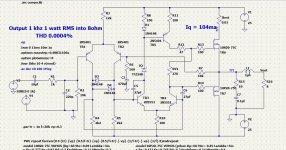
You are measuring wrong the distortion. In post 28 I get 0.00038% 1w 1khz and 0.0053% 20khz.
You need to let 10 cycles before start saving data for only one cycle.
Short the output inductors.
That's slightly better 🙂 Thanks for noticing, I'm still learning how to use spice.
Say something like this.
Ok, see that you mean this cascade currents source now. But do you really think that two transistor current source is such a bad choice for this amp? It's used in a lot of input stages, of much more higher performance amplifier than this one.
Further correction
However, this resistor creates a mirror effect on Q4 and prevents Q4's collector current from being accurately transferred to the input of the high-side current mirror.
→ However, this resistor creates a millor effect on Tr3 and prevents Tr3's collector current from being accurately transferred to the input of the high-side current mirror.
Last edited:
Two-transistor CCS from secong image in your post are good too.Ok, see that you mean this cascade currents source now. But do you really think that two transistor current source is such a bad choice for this amp? It's used in a lot of input stages, of much more higher performance amplifier than this one.
But shown Hawksford's CCS are the best in terms of output resistance because it compensates output transistor base current while two-transistor CCS have the lowest voltage headroom to operate.
H
HAYK
H
HAYK
The diodes limit the vas current on saturation. The purpose of R9 is to equal the collector voltages of the differential, the zener alone does the same.
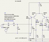
The crossover distortion exhibit at H5, it must be lower than H4 and still not the case. May be with 175ma bias?
You need to work on the loop gain to have higher NFB @20khz. The two 27pf must be replaced with other type of pole, maybe CRC between the bases to get 2pole compensation.
The crossover distortion exhibit at H5, it must be lower than H4 and still not the case. May be with 175ma bias?
You need to work on the loop gain to have higher NFB @20khz. The two 27pf must be replaced with other type of pole, maybe CRC between the bases to get 2pole compensation.
H
HAYK

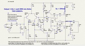
Yeah.Instead of 50db NFB@20Khz it is now 70db for finest high frequencies.
Now let's add some degeneration in LTPs.
And...
Maybe...
Two LTPs more?
PS.
Silicon chips magazine, june 1994, Antony Eric Holton.
H
HAYK
Well that is very impressive! Only 0.005 % at 20kHz... I'll have to try the two pole compensation network then I get time again. Assuming this is what lowered the distortion at high frequencies.
Regarding the input impedance. It was never my intention to keep that high anyway. Was thinking that about 10k would be enough.
Never simulated the circuit with higher bias current than 100ma actually. Keeped it at the level for comparsion. Then I build the actual amp I will probably connect it to distortion meter and then adjust the bias to lowest distortion.
I'm still reading 🙂
Why not build an original as it was well received and proven and then work on something that might better it 🙂 You then have the original to compare against.
Why not build an original as it was well received and proven and then work on something that might better it 🙂 You then have the original to compare against.
Yes, loop depth is the main way to reduce distortion when OPS are well enough.I'll have to try the two pole compensation network then I get time again. Assuming this is what lowered the distortion at high frequencies
No.Regarding the input impedance. It was never my intention to keep that high anyway. Was thinking that about 10k would be enough.
Since your scheme will work with volume regulation pot in needs very high (at least 10 times, better 100) input resistance and neglible dynamic capacitance at common and differential modes.
Should we sign that we haven’t learned anything in 30 years?Why not build an original as it was well received and proven and then work on something that might better it
😀

No.
Since your scheme will work with volume regulation pot in needs very high (at least 10 times, better 100) input resistance and neglible dynamic capacitance at common and differential modes.
Wasn't planning to put a pot in front it, but a preamplifier.
Should we sign that we haven’t learned anything in 30 years?
Absolutely we have 😉 we have learned to move that decimal point ever more to the left but that doesn't always translate into a more pleasing musical result 🙂
Clearly!we have learned to move that decimal point ever more to the left but that doesn't always translate into a more pleasing musical result
We measure and optimize something, that doesn't straightly defines sounding.
This results in a deep optimizing of more and more issues/noises/errors but doesn't provide according benefits in sounding. Thus frustrating.
Hmmm.Wasn't planning to put a pot in front it, but a preamplifier.
Other external case or in one common case with amplifier?
Hmmm.
Other external case or in one common case with amplifier?
External case, but no long cables between (>1m). Thought 10k would be a appropriate input impedance, like to keep as low as possible.
- Home
- Amplifiers
- Solid State
- VAS requirements for MOSFET OPS