Yes you're right again. Luckily it will be a easy fix to flip those diodes at the finished PCB.
Yesterday I finished a board based on the latest design. It tested OK, pretty exactly as the prototype, which was good. However, since it has shown that changing the input current just slightly greatly affects the VAS current, which is a key factor for distortion, this kept me awake at night.
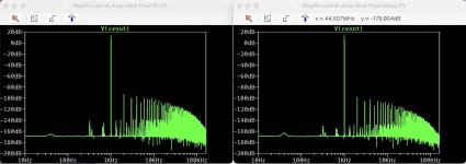
So I just had to try increasing the current using a trimmer in series with a resistors instead of R4, and the results were promising. Distortion dropped by just increasing the current so very slightly. Settled at a fixed resistor of 620 ohms for R4 instead of 680 ohms as before. This increased the input stage current from about 0,98 mA to 1,08mA. And then the VAS current was increased from 4.95mA to 5,56mA.
The distortion figures are now even more impressive. Especially at higher frequencies and for 4 ohms load (which it is a very big chance that this amp will be driving);
0.0016 % THD 1khz 1W 8 ohm 0.0015 % 1khz THD 1W 4 ohm
0.0025 % THD 1khz 18W 8 ohm 0.0023 % 1khz THD 25W 4 ohm
0.0008 % (2nd order) 10khz 1W 8 ohm 0.0008 % 10khz (2nd order) 1W 4 ohm
0.0025 % (2nd order) 10khz 18W 8 ohm 0.0020 % 10khz (2nd order) 25W 4 ohm
The maximum power output (without too much distortion) may have dropped a few watts from 20 to 18W for some reason. I have no idea why, but everything else seems ok and slew rate is still 20-25V/µS. So far this is looking like a pretty good project I think.
Attachments
The reason for the decrease in maximum output is that by increasing the current in the first stage, the voltage across R3 and R5 increases, and accordingly, the voltage across R10, R8, and R11 of the VAS also increases, the possible swing range of VAS becomes narrower.
You can increase the output a little by lowering those resistors, but it's only a small difference, so if you don't care, you can leave it as is.
It's good that the project is heading in the right direction. However, I think it would be even more gratifying if your understanding of circuits deepened and your skills improved.
I wish you all the best in your future development.
It's good that the project is heading in the right direction. However, I think it would be even more gratifying if your understanding of circuits deepened and your skills improved.
I wish you all the best in your future development.
Thanks, I'm still learning. This has been a very educational project for me. I'm very grateful for all the help I've received from you, and others, during the process.
bengtssk:
is your project officially finished? what does you final schematic look like? are you still happy with your measurements? remember that the articles mention the importance of the output coil at lowering high frequency distortion and routing of grounding wires, etc. will impact your measurements, too. it's a relatively simple circuit with a lot of potential. glad you had good results and good learning!
🙂
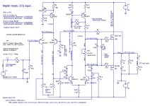
Yes, it's finished now, @mlloyd1 . Right now it's sitting at my desktop and drives two bookshelf speaker for my work room. The amplifier handles this task great, with it's 25W of power or so. The sound is great, much clearer and detailed than the earlier TDA2040 amp. Tried it with bigger speaker in the living room, but that was of course asking to much of it. However for this task that it was design for its doing great. The 160 VA transformer that drives probably helps. With 4 or 5 inch book self speakers, the amp doesn't sound "weak" at all.
The final version schematic is attached. I can upload a Kicad/gerber file for the layout as well if you're interested. As you can see from the pics it's quite simple design; one layer hand made PCB.
After the success with the first board, the second board tested slightly worse though. Maybe I got lucky with the first one, very good transistors or caps? Tried replacing the caps in the VAS from MLCC to single layer NP0's, but didn't affect the results a lot I think. The numbers from testing of the second board was as;
0.0041 % THD 1khz 1W 8 ohm 0.010 % 1khz THD 1W 4 ohm
0.0067 % THD 1khz 18W 8 ohm 0.013 % 1khz THD 25W 4 ohm
0.0040 % (2nd order) 10khz 1W 8 ohm 0.010 % 10khz (2nd order) 1W 4 ohm
0.0070 % (2nd order) 10khz 18W 8 ohm 0.013 % 10khz (2nd order) 25W 4 ohm
Input sensitivity approx 1,2V rms
Slew rate about the same; 25 v/µS
Of couse I wish that I could make those numbers better, specially for 4 ohms. Maybe I should mesarue the amp again and see if somehting changed... It was I really interseting project this one, and I learned a lot.
Attachments


That looks fantastic, really nice build!Right now it's sitting at my desktop
This thread was unknown to me, I was looking and learning a similar route on the Maplin MOSFET amplifier, and it's very interesting to see where we coincide and vary!
See: (This is also sounding superb, still listening, got some first real listening in yesterday!)
https://www.diyaudio.com/community/...ga28f-construction-thread.257488/post-7644501
We concur on the CCS on the Input LTP, I run mine a bit harder, as recommended by Douglas Self's webpage, 3.52mA, the VAS runs at 6.1mA, a little low (but not so hot!), perhaps I'll substitute a 2SA1145 / 2SC2705 pair in another build to get it up to about 12mA.
Good to see you get rid of the 6n8, as it messes up the +ve clip, creating a nasty hollow/invert there. I also found I needed a 'bootstrap' 270k resistor, as I found the VAS can be lazy to 'pick up' the gates when TR5 is fully on, with certain component value combinations, so that stops any of that nonsense!
I also found that rail isolation has a benefit to the sound, so I use a couple of schottkys damped with resistors in series to feed the driver, so power line sags don't impact the driver section.
One day I'll perhaps get a PCB made with the PSU and all on the same PCB, just to get everything neat!
Thanks, nice to hear that you appreciate it. And what a coincident @Globulator ! Just read your post, see that you also use 2n5401/5551 for VAS and input stage. May be a little to much for them to handle 12 mA in the VAS though depending of your supply voltage. The only reason I stuck with them for VAS was just for simplicity, no need to use bigger transistors (like 2SB649/2SD669 or similiar) if you don't have to right?
Yeah that damned 6n8 cap... had a hard time understanding it. However did not see that it messed up +Ve clip, but maybe I ddin't look for it either, interesting though. The main benefit I got from substituting 6n8 cap andk 12 k resistor with transistor Q4 was to get rid of some DC offset in the final design. Still not sure why it did, but try it your self.
Unfotrunately, I discovered something very dissapointing today. Measured the distortion again and discovered that the distortion was almost 10 times higher at tthe right channel. Mearured about 0,0021 %THD 1W at 1khz 8ohm for left channel (first board) and 0,01% at right channel (second board)! Thought the quiecsent was off, but it was the same at about 100 mA for both channels. Increasing the quiescent current to something really high like 200-300mA gets rid of most of the distortion, down to like 0,005% or so.
Because the distortion goes away by increasing the current, I guess it has to be the output devices that is causing the distortion. The boards are excatly the same, this is so strange. Maybe I should get som new MOSFET's and try? Can they differ so much?
Cheers, yes it's interesting to compare notes!the distortion goes away by increasing the current
i was a but puzzled when you said it ran out of steam on the big speakers, I had mine on 22V rails for some testing and it was hugely loud - but then again my test speakers are 12" Eminence Beta 12s with Motorola Bullets - so I'm probably a few dB louder for the same input - but 20W would move some air!
I did a long FFT on the design at various levels, and it seems Class A is almost distortion free:
https://www.diyaudio.com/community/...ga28f-construction-thread.257488/post-7635217
So I suspect you 'cured' it by moving into class A with the increased bias.
IMO it's a combination of crossover distortion, and the speed of the circuit to be able to correct it.
The crossover is a very small slice of time, and even at 1kHz is still requiring a very very fast correction - so I'd also look to see if the capacitors are correct in the RH channel, i.e. anything that may slow the loop down or reduce the open loop gain.
The ultimate test would be to swap over the boards, with the other's output transistors - a hassle - but would narrow down the issue.
I'll be trying the Q4 trick!
I added the 2 pole filtering to my schematic but LTspice didn't like that, so I'll have to see why!
I tried a number of values in the 6n8, but each time it caused it's own problems, also it's absence created a useful space on the PCB to add the 270K bleed resistor, the 'emergency lift' for the gates if TR5 switches off completely. 😀
I used the 2N5401 for the CCS, and for simulation with the 2N5551, but the other transistors are the original 1980s ones in my board - so I left them! Even at 6.2mA they get warm, 41C I measured in a garage of 17C, but they have stood the test of time and I think the original current was around 6-6.5mA.
The Mosfets have gate capacitance but as they follow it's not so bad, but a new build would use the bigger transistors - or a MOSFET VAS if I could get it to a low enough distortion!
i was a but puzzled when you said it ran out of steam on the big speakers, I had mine on 22V rails for some testing and it was hugely loud - but then again my test speakers are 12" Eminence Beta 12s with Motorola Bullets - so I'm probably a few dB louder for the same input - but 20W would move some air!
Well it wasn't a fair test. Compared it to my Vincent SP-331, 150W per channel at 8 ohms. Driving some really heavy Swan speakers, probably around 86dB sensitivity or so. It's not that bad....
Main benefit from two pole is stability I think, that's why it used it anyway. What didn't LT spice like about it?I added the 2 pole filtering to my schematic but LTspice didn't like that, so I'll have to see why!
My 2N5551 transistor gets a little warm to touch, but not a problem. With 6 mA VAS current they'll dissipate about 300mW, well within their specs.
I thought it got stuck, after a few microseconds, sometimes simulators do this - but now I see that when I dragged some of the circuit to create space, I disconnected some vital wires too 😀What didn't LT spice like about it?
Ok, so having reconnected those, on my circuit, just changing to 2pole I get (0.2V in, 6.5Vpk out)
LTSpice distortion single pole 33p
Partial Harmonic Distortion: 0.000773%
Total Harmonic Distortion: 0.000530%
LTSpice distortion two pole 47p 1k 470p:
Partial Harmonic Distortion: 0.000398%
Total Harmonic Distortion: 0.000000%
So that's good!
The spectrum is better, so this is definitely affecting the overall circuit well.
I'll try Q4 later, when I get a chance!, and maybe some square waves..
Attachments
BesPav:Try this mirror-biased two-stage follower OPS.
It will greatly expand bandwidth, soften shoulder transition, allow for huge VAS loading resistor nominals and overall improvement in amplifier's open loop depth with corresponding lowering of THD figures.
I meant to ask this months ago - what is the purpose of D28, D29 and R156 in your output stage?
LTSpice distortion two pole 47p 1k 470p:
Partial Harmonic Distortion: 0.000398%
Total Harmonic Distortion: 0.000000%
So that's good!
The spectrum is better, so this is definitely affecting the overall circuit well.
I'll try Q4 later, when I get a chance!, and maybe some square waves..
Nice. Even if your real nummers will never be close too that, it's an improvment at least.
You should definitely try that. And check the squarewave response...
Also try some different values of the two pole caps and resistor. As a rule of thumb the second cap should be about ten times bigger as the first one. Which is equal two the single pole capacitor. The resistor value of 1k is common. But try some different combinations, keeping the ratio between the caps about 10. Had some interesting effect of the squrewave response I think.
Aargh... This is a voltage source parts for different design with common base VAS.I meant to ask this months ago - what is the purpose of D28, D29 and R156 in your output stage?
Forget to remove.
- Home
- Amplifiers
- Solid State
- VAS requirements for MOSFET OPS