Hi Stretchneck
You mean 2 stereo sets of USSPA?
for the USSA-8 Turbo there is no dedicated pcb so you need to use USSA 5 pcb and run wires for the additional pairs of outputs. I am not sure I want to free my remaining stock of these obsolete mosfet…please contact me by personal message…
Alternatively you can build an USSA-5.2 Twin Turbo for a “similar “ sound…
Fab
I would love to build the USSA3 Turbo with cascoded JFet front end and two pairs ECW20P20/N20 power mosfets. Just how is the USSA3 with a higher voltage (36 VDC rail voltage) for a higher power even if not biased all the way to Class A. A la Pass F5 and F5T. I would love to have (to know, to be sure) a working schematic (at least simulated) even if will never have a PCB layout or PCB. It came to me as love at first site when I saw the USSA3 with JFet in signal. I know this is not a wish programHi Fab,
Apologies:
2PCBs USSPA
4PCB's USSA-5.2 Twin Turbo
+ build instructions.
Yes your right, best to stick with USSA-5.2 Twin Turbo - can use the readily available ECW20P20/N20 if I understand correctly.
 . To bad, Thanks Fab for all!
yes, you are right.Hi Fab,
Apologies:
2PCBs USSPA
4PCB's USSA-5.2 Twin Turbo
+ build instructions.
Yes your right, best to stick with USSA-5.2 Twin Turbo - can use the readily available ECW20P20/N20 if I understand correctly.
I have received your payment but for 2PCB of USSA not 4.
please advise.
Fab
Hi GaborbelaI would love to build the USSA3 Turbo with cascoded JFet front end and two pairs ECW20P20/N20 power mosfets. Just how is the USSA3 with a higher voltage (36 VDC rail voltage) for a higher power even if not biased all the way to Class A. A la Pass F5 and F5T. I would love to have (to know, to be sure) a working schematic (at least simulated) even if will never have a PCB layout or PCB. It came to me as love at first site when I saw the USSA3 with JFet in signal. I know this is not a wish program
I have made so many USSA variations and yet you want another one
have in mind that FSSA-1 or 2 is somewhat similar to what you describe but with one double die pair and follower as output though. USSA-7 is also even more similar but using double pairs of 2SK1530/J201 as output. So you would want an hybrid of USSA-7 and USSA-8…
Fab
Last edited:
I will send you a private message, maybe a email so I can attach a schematics!
I do not want to post here, it have most resistor values in the schematics I would love (plan) to build.
I must send a schematics so we can discuss it without any confusion.
I have some problem to set up the USSA5 with those small Jfets)see the attach) and those resistors which must be calculated.
I do have a stuffed pair PCB with all (exotic) parts except those 2x2 Pc (stupid) resistors no-one knows the values unless calculate.
I do not like those, those stopped me to finish the amp at the last 2-3 years.
First off all I do not want to burn or explode the whole thing.
Those Toshiba driver mosfets getting rare, hard to find pieces, I only have 4 matched pairs.
I still remember when I built an amplifier from Dr. Jagodic (RIP) and the whole thing blew into my face at power up!
The large Sanken transistor case exploded into my forehead.
It was a proven circuit and layout, built amp by several DIY-ers.
I think because of that experience (plus suffering from PTSD) I will give up this project and try something with out the mentioned calculation (find out
resistors values), tricky set up.
That amplifier ("Cascoded" Turbo USSA 3) I mentioned it does not required that type of set up, measurements where I need at least 4 DMM etc.
I don't know much about the First W 7 unfortunately I stopped following after F6 and M2 variations. Greetings
I do not want to post here, it have most resistor values in the schematics I would love (plan) to build.
I must send a schematics so we can discuss it without any confusion.
I have some problem to set up the USSA5 with those small Jfets)see the attach) and those resistors which must be calculated.
I do have a stuffed pair PCB with all (exotic) parts except those
2x2 Pc (stupid) resistors no-one knows the values unless calculate.I do not like those, those stopped me to finish the amp at the last 2-3 years.
First off all I do not want to burn or explode the whole thing.
Those Toshiba driver mosfets getting rare, hard to find pieces, I only have 4 matched pairs.
I still remember when I built an amplifier from Dr. Jagodic (RIP) and the whole thing blew into my face at power up!
The large Sanken transistor case exploded into my forehead.
It was a proven circuit and layout, built amp by several DIY-ers.
I think because of that experience (plus suffering from PTSD) I will give up this project and try something with out the mentioned calculation (find out
resistors values), tricky set up.
That amplifier ("Cascoded" Turbo USSA 3) I mentioned it does not required that type of set up, measurements where I need at least 4 DMM etc.
I don't know much about the First W 7 unfortunately I stopped following after F6 and M2 variations. Greetings
Attachments
Maybe something like this could help for making the double output versions? Just a quick draft without board mountingholes etc. FSSA-2 board is stacked on this breakout board using spacers and short pieces of wire making the contact between breakout and mainboard. Example would be compatible with the UMS.
@fab: What about thermal compensation when using the 1530/201 as they are verticals?

@fab: What about thermal compensation when using the 1530/201 as they are verticals?
Hi Gaborbela
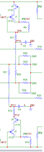
if you use the nominal values indicated in schematics for USSA-3.x lateral mosfet version it will definitely work without breaking anything ( that is the purpose of the nominal values indicated). Adjusting these 2 specific resistors values is just for optimization. In practice after many builds and different lots of ECW mosfets I concluded that the ratio between N and P mosfet channels is always about between 1,4 to 1,6. so if you simply use 1,5 it should be optimized enough for the purpose. Thus,
(R13 + RV1) / (R14 + RV2) = 1,5.
only need to measure one VGS at 1A bias and you will get both positive and negative sides values. In any case, if you provide one measurement only at one specific output bias current I can extrapolate for you the optimized values.
if you build output BJT versions, since VBE has only very minor difference compared to mosfet VGSoff threshold, the fixed value is provided in the schematics for these 2 specific resistors values.
mosfet drivers have been repacked by alternative ones in versions 3.2 or 5.2, see first post.
you need only 2 multimeters of one meter ans one scope for adjustments.
ok I will await your e-mail.
Fab
The one amplifier I have and run into the mentioned problem that is the USSA-5.2. Maybe I was not as clear.
Because of the mentioned problem I would love to build the USSA-3, the same time why not upgrade it to a Turbo, for higher power.
I have a Class D power mosfets, same factory as Exicon but from different supplier from England. I am not sure it is the 100% the same, they said yes.
I don't know if that (the power mosfets) required the mentioned (measurements and resistors value calculation) or just powered up?
So you say if I use 2X2Pc 1.5R resistor that should work? I know I must set up the bias and the offset!
We are talking here about that 2X2Pc resistor to set up who knows what, I was instructed I must calculate them so that was the end of the USSA project.
I will write soon.
Greetings
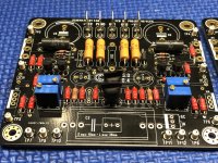
I have the same PCB like the attach.
Because of the mentioned problem I would love to build the USSA-3, the same time why not upgrade it to a Turbo, for higher power.
I have a Class D power mosfets, same factory as Exicon but from different supplier from England. I am not sure it is the 100% the same, they said yes.
I don't know if that (the power mosfets) required the mentioned (measurements and resistors value calculation) or just powered up?
So you say if I use 2X2Pc 1.5R resistor that should work? I know I must set up the bias and the offset!
We are talking here about that 2X2Pc resistor to set up who knows what, I was instructed I must calculate them so that was the end of the USSA project.
I will write soon.
Greetings
I have the same PCB like the attach.
Attachments
Hi nfsgame
yes that is a good idea. As per Vunce saying the pcb seems oversize a bit…. Maybe the option of 2 remote pcbs on each side of the original one… there ate also twin turbo versions using USSA pcb…
As for the vertical mosfet thermal compensation, it is taken care of with the schematics values and heatsink requirements stay the same.
Fab
Something like this? 40mm pitch between mosfets, 65mm between screws, terminals for high current connections could be soldered wire or TE 8191. Capacitor footprint is 5mm/12,5mm - could be either Rubycon RX30 1000uF/35V or 330uF/63V. Snubber for each FET optional if there are oscillations because of the remote mounting. PCB-dimensions 40*100mm

- Home
- Group Buys
- USSA-5 PCB GB