Right , thanks for the lightening fast response .
For , 2sk2013Y and 2sj313Y 's the manual says the current should be 23 to 28 mA
What bias current range do you recommend for FQP3n30's and FQP3p20's ?
.
For , 2sk2013Y and 2sj313Y 's the manual says the current should be 23 to 28 mA
What bias current range do you recommend for FQP3n30's and FQP3p20's ?
.
Fab ,
Thanks for this . I was thinking in terms of what is enough current to effectively drive the Ciss of the Exicon ECW20 MOSFET's .
But then running the FQP3 MOSFET's at a good linear operating point would come into play as well .
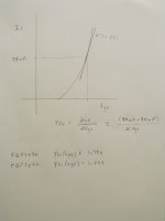
Looking at the datasheet of a FQP3n30 , there is a graph showing the transfer characteristics
https://www.mouser.ca/datasheet/2/308/1/FQP3N30_D-2314058.pdf
Yfs = delta Id / delta Vgs , but this only goes down to 100 mA .
.
Thanks for this . I was thinking in terms of what is enough current to effectively drive the Ciss of the Exicon ECW20 MOSFET's .
But then running the FQP3 MOSFET's at a good linear operating point would come into play as well .
Looking at the datasheet of a FQP3n30 , there is a graph showing the transfer characteristics
https://www.mouser.ca/datasheet/2/308/1/FQP3N30_D-2314058.pdf
Yfs = delta Id / delta Vgs , but this only goes down to 100 mA .
.
Underhill
the lateral mosfet has quite low Ciss compared to vertical mosfet. So 70ma of drive is sufficient and yes the more linear part of the transfer curve is better but at the expense of more power dissipation. These transistors are rather meant to be used in low/medium power stage so that is probably why the curve does not show for lower current….70 should be similar to 100ma and should be enough, everything is a compromise anyway….
Fab

Fab ,
Unfortunately , I got caught up with silly things like bathroom renovations and other projects ,
so the USSA 3.2 was put on hold for a while .
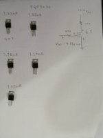
So I just tested some FQP3n30's and FQP3p20's using a different method than what Nelson Pass used .
Since Vgs controls Id , I tested them by setting Vgs to a constant and then measured Id .
In general , for the same Vgs , Id was considerable higher for the p type rather than the n type .
The MOSFET's take a while to warm up , so that's why I set Vds and Id on the low side when testing them .
Unfortunately , I got caught up with silly things like bathroom renovations and other projects ,
so the USSA 3.2 was put on hold for a while .
So I just tested some FQP3n30's and FQP3p20's using a different method than what Nelson Pass used .
Since Vgs controls Id , I tested them by setting Vgs to a constant and then measured Id .
In general , for the same Vgs , Id was considerable higher for the p type rather than the n type .
The MOSFET's take a while to warm up , so that's why I set Vds and Id on the low side when testing them .
Attachments

Last edited:
UUnderhill
Yes bathroom is a different kind of work….🙄
Your method is not correct for this application. The threshold voltage is just a parameter and does not give the vgs-Id curve. If the N channel and P channel have different voltage threshold starting point it is no big deal because in the end it the source current that matters. You should rather test for a same transistor the Id for different VGS value . It is around the used driver bias current that it can matter. If the transconductance (Yfs) is about the same at about half , used and double current than it means you are in the linear part and also you have a good match between N and P channels for the transconductance. The detailed method to calculate the transconductance is in the build manual..if you have genuine parts - as determined by transconductance measurements- then you should not even worry too much about a close transconductance perfect match in this topology.😉
Fab
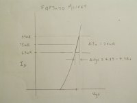
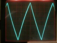
FAB ,
You are right about the current required for the FQP3 mosfet's .
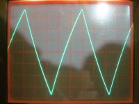
The test frequency shown was 10 KHz .
When Id = 25mA the waveform was compressed .
But when Id was pushed up to 75mA the linearity improved .
.
You are right about the current required for the FQP3 mosfet's .
The test frequency shown was 10 KHz .
When Id = 25mA the waveform was compressed .
But when Id was pushed up to 75mA the linearity improved .
.
Attachments
" ... in the end it the source current that matters. You should rather test for a same transistor the Id for different VGS value . It is around the used driver bias current that it can matter. If the transconductance (Yfs) is about the same at about half , used and double current than it means you are in the linear part and also you have a good match between N and P channels for the transconductance. ... "
I've read your comment carefully , as well as the booklet .
Hopefully , I understand this correctly .
Since its the source current that matters , should I try to find an n and p MOSFET where Yfs matches at 75 mA ???
The datasheet for the FQP3n30 says Yfs (typ) = 1.75s
and FQP3p20 Yfs (typ) = 1.23 s
.
Attachments
Uunderhill
You are on the good path but trying to find the same yfs between N and P is maybe too ambitious…. Better to find same yfs for both left and right audio channels (thus N with N, P and P) so left and right channel behave similarly (especially in low overall feedback design). If N and P channels are both in the linear part of the curve at the intended bias current then it is correct.
Fab
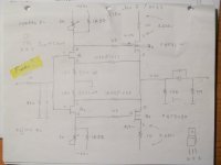
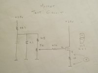
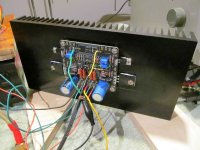
Trying to measure Yfs , I modded a section from one of Nelson Pass's Amps to create a test circuit .
Id was set by adjusting the 5K pot .
The problem is delta Vgs is so small , a really accurate way of measuring Vgs is required , to obtain delta Vgs .
Also the MOSFET's need to warm up before taking a measurement ... which is a total pain .
Also , tried building an amp to measure Av ( the voltage gain ) .
Once knowing Av , Yfs could be obtained .
But this didn't work out .
A 3rd method would be to build a differential pair with 2 MOSFET's . Add a signal to both MOSFET's .
Then if Vout = 0 , then the 2 MOSFET 's are matched .
Attachments
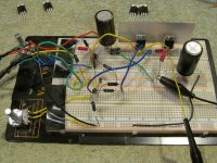
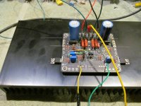
The good news is that the circuit works beautifully with the FQP3 MOSFET's .
The very slight asymmetry in Vout is caused by the 40 year old scope .
You really notice the quality of the circuit board when plugging in the disconnects .
Warm Up Time Required - note the thermistor is not in the circuit , and there wasn't any heat sink compound
time ........... Id for the FQP3 MOSFET's
0 ................. 63.5 mA
6 min ........... 72 mA
16 min ......... 73 mA
30 min ......... 73.2 mA
80 min ......... 74 mA
So as the FQP3 MOSFET's warm up , they conduct more .... and take about an hour to reach operating temp .
But the Exicon MOSFET's are lateral MOSFET's .
From what I understand , as lateral MOSFET's warm up , they conduct less .
So if the two temp co coefficients have opposite slopes , can the thermistor be left out of 3.2 version ?
.
Attachments
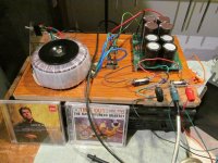
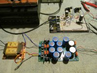
So I increased the current on the USSA 3.2 slowly , first with a bench power supply and then switched to the 300 VA supply shown below .
Note the 3 Amp fast blow fuses on the + Ve and - Ve of the 300 VA supply .
Without the thermistors , the amp took about at 60 minutes to reach full bias current .
The amp is so well behaved . The DC offset on Vout only drifted from +19 mV to - 6.0 mV as the amp was warming up
before settling down to 0.1 mV .
The amp has only had about 6 hours of running time .
DiyAudio member Pinnocchio said to give these amps 30 to 50 hours of burn in time .
But so far the bias currents are
.......................... n ................................... p
FQP3 's ........... 54.1 mA ........................ 58.9 mA
Exicon 's .......... 1.22 A ............................1.22 A
Test set up
Harmon Kardon 7600 MkII CD player ===> USSA 3.2 Amp ==== > B&W 110 speakers
Listening to Mozart Piano Concerto No. 20 ( Leif Oves Andsnes - aka the Vikings Play Mozart )
First impressions of the USSA 3.2 ... you get really drawn to listening to timbre of the piano and listening to the music .
With the USSA 3.2 you realize just how good the piano is used in this recording .
.
Attachments
Last edited:
An update on the USSA 3.2 Amp
- Putting my ear right beside the mid/bass driver of the B&W 110's , the amp is so quiet can't even tell its on until the music starts playing .
- After about 50 hours of break in time , the USSA 3.2 really pushes these speakers around . The sound is very dynamic .
There is a lot to be said for a great amp driving Mid Fi speakers . You get drawn into listening to the timbre of each instrument .
For example , it really stands out when Joe Morello ( Time Out ) is using the brushes , as opposed to the sticks .
The amp is so good , I left this set up on the bench and used as a Right Channel only system for a while .
- However , IMO the amp sounded better at certain times of the day , so plan to up grade the basic CRC power supply .
Will add a Fo Felix EMI filter and Hammond 159ZL chokes .
- Looking at the datasheet for the Exicon ECW20x20 MOSFET's , it does not show the metal back of the case is connected to the source .
But it is . Have no idea how this amp worked without thermal pads ... but it did .
https://www.exicon.info/PDFs/ecw20n20.pdf
After , receiving great amount of advise from DIYAudio members on the issue of thermal pads , have decided to go with AL2O3 pads .
Aavid 8120G thermal pads have a thermal conductivity of 79 W / ( m x k ) .
https://www.mouser.ca/c/thermal-management/thermal-interface-products/?m=Aavid&thermal conductivity=79.56 W/m-K
- When connecting the amp in the final build , I still connected fast blow fuses between the power supply and the amp .
Highly recommend doing this when testing or setting up any amp .
Last edited:
@Uunderhill
You're totally right about the amp being totally silent. For me it's the same thing, even with my ear directly on the tweeter or mid/bass drivers, nothing comes out until you start playing music, and the only reason why I know the amp is on is because of the power switch light.
I've build many of Fab's amplifiers and they're all amazing amplifiers. At the moment I have the USSA 3.2b Turbo, the USSA 5 and the FSSA 2, love them all and also all keepers! 🙂
I'm happy you love the amp and hopefully it will bring you emotions and happiness for many years to come!
Best!
Do
@ pinnocchio
Which of the pre-amps you use with these power amps do you consider to be the most musical?
Thanks
Which of the pre-amps you use with these power amps do you consider to be the most musical?
Thanks
Brianco ,
IMO one of the keys to a great preamp is having ultra quiet supply rails .
So highly recommend - Fo Felix DIY EMI filter followed by a dual bobbin transformer .
r core transformers can be difficult to source , and E core transformers can hum .
So suggest the Hammond 229 Series , but these need to be mounted on a circuit board .
https://www.hammfg.com/electronics/transformers/power/229
As shown in the photos attached , I use a clipper power supply .
The clipper just takes a pair of scissors , and cuts the top right off the rectified waveform .
Then this is followed with a 4th order Low Pass Filter . This may be a bit crude , but its ultra simple and it works .
Actually , if you look at the schematic of the famous Marantz model 7 preamp ,
you'll see it uses a multiple stage LPF .
Another option , AMB Labs Sigma 22 power supply board , which has a very positive reputation .
https://www.amb.org/audio/sigma22/
The third option is a shunt regulated supply .
This 4 part series discusses noise figures on the supply rails with various power supplies and batteries .
https://www.tnt-audio.com/clinica/regulators_noise1_e.html
.
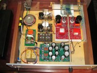
Please ignore the wiring mistakes in the tube preamp - its on my to do list to fix them .
Regardless , this cathode follower design sounds amazing .
To point out these are 6gm8 ( ecc86 ) tubes , which were a low voltage tube designed for car radios .
.
IMO one of the keys to a great preamp is having ultra quiet supply rails .
So highly recommend - Fo Felix DIY EMI filter followed by a dual bobbin transformer .
r core transformers can be difficult to source , and E core transformers can hum .
So suggest the Hammond 229 Series , but these need to be mounted on a circuit board .
https://www.hammfg.com/electronics/transformers/power/229
As shown in the photos attached , I use a clipper power supply .
The clipper just takes a pair of scissors , and cuts the top right off the rectified waveform .
Then this is followed with a 4th order Low Pass Filter . This may be a bit crude , but its ultra simple and it works .
Actually , if you look at the schematic of the famous Marantz model 7 preamp ,
you'll see it uses a multiple stage LPF .
Another option , AMB Labs Sigma 22 power supply board , which has a very positive reputation .
https://www.amb.org/audio/sigma22/
The third option is a shunt regulated supply .
This 4 part series discusses noise figures on the supply rails with various power supplies and batteries .
https://www.tnt-audio.com/clinica/regulators_noise1_e.html
.
Please ignore the wiring mistakes in the tube preamp - its on my to do list to fix them .
Regardless , this cathode follower design sounds amazing .
To point out these are 6gm8 ( ecc86 ) tubes , which were a low voltage tube designed for car radios .
.
Attachments
Last edited:
Brianco ,
If you haven't seen this , I highly recommend getting a print out of this 2 part series by Erno Borbely .
https://audioxpress.com/article/JFETs-The-New-Frontier-Part-1.html
For solid state preamp , I prefer a " Mini Me " F5 topology over a differential pair .
So if you have a source for 2sk2013 and 2sj313 's , I'd say build FAB's USSPA preamps.
However , if you can't get a hold of these MOSFET's , consider using Exicon single die ECX10n20 and EXC10n20's , as I've shown above .
Many of the resistor values will need to be changed .
For the preamp circuit board , I'm thinking FAB's and Project 16 / Alex USSA 5.0 rev 0.4 could be used by adding jumper wires ,
and leave out the driver MOSFET's .
Or you could use DIYAudio Stores F5 boards , but will need to mod them because the pin out of an IRFP240 and EXC10n20 is different .
.
WARNING : Subjective Comment . Since you are after " musical " .
The sound quality of most 1980's DDD CD recordings of classical music is horrific .
This performance by Christophe Coin of Haydn's Cello Concerti is spiritual - especially the Cadenza
when he bounces the bow on the strings . But the 1985 DDD recording quality is criminal .
https://www.discogs.com/release/324...W8dNQzwNmrcHIrGqCv6MtX5HiroA5k46H5o_EhXVJtRPc
I conducted a subjective listening test with a number of film caps fabricated for audio .
IMO the Clarity CSA series makes this recording listenable .
Suggest by passing the ClarityCap CSA with either Sprague Orange drop 10nF 716p series cap or a 8.2 nF Russian Silver Mica .
Subjective Comment Ended .
.
Brianco , A few more points .
You'll notice FAB spends quite a bit of effort taking measurements of the Harmonic Distortion of his Amps .
They typically have 2nd and 3rd order harmonic distortion , and then there is almost nothing from the 4th order and above .
I think this is the reason why FAB's designs are so musical .
Many people find harmonic distortion , from the 4th harmonic and up , objectionable .
The " mini me" F5 preamp I have shown above is biased at 100mA . The last pair of caps on the 4th order filter are 8,200uF each .
I'm still having a tough time believing this , but the music shows up on the supply rails , even with all those caps .
So consider building a power supply for each channel .
Should add the reason why I think its best to go with dual bobbin transformers on a preamp
is that they have low capacitive coupling between the primaries and secondaries .
.
Last edited:
- Home
- Amplifiers
- Solid State
- USSA-3B new Version based on USSA-3