
" I am more concerned with getting the [ USSA 3.2 ] boards up and running. "
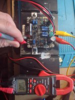
" Will be using a VRDN board as my temp power supply to test the boards before hooking everything up. "
" ... for most of my first watt clone builds, "
If you've built an F5 , the USSA 3.2 is just the next step .
To get used to the circuit board layout , suggest using a pencil and paper
and sketch out where J1 , P1 , M3 and R13 are physically located ... and then where J2 , P2 , M4 , and R14 are located .
Do you have signal generator and a scope ?
Start with P1 and P2 fully counter clockwise .
Just like with an F5 , turning the trimmers clockwise will increase the bias current .
Then you'l start to see the waveform coming to life on the scope .
Again , I checked the bias current of the FQP3's by measuring the voltage drop across R13 and R14 .
I havent built the F5. But all of this really helps, thanks guys, will take me a bit to get the boards mounted on the heatsinks.
Years ago on DIYAudio , I was sternly told by a very experienced Audio builder , that the power switch must switch both the Hot and Neutral .
However , I was just advised this is not correct . Here in Canada CSA sets the standards for appliances ( ie Amplifiers ) .
Canadian Standards Association clearly states that the power switch should only break the Hot and NOT the Neutral .
.
Same story in the US . For UL-listed appliance switches, you should always switch the hot wire, not the neutral. Switching the neutral can create a dangerous situation where an appliance still has power when switched off, potentially leading to electrocution.
.
Its seems that I was given bum advise yesterday .
The person was referring to the Electrical Code ... which is the regulatory body for Residential and Commercial wiring .
Totally agree that for a household light switch , only the hot should be switched
and the neutral should NOT be switched as it provides a return path back to the panel .
However , in Canada , CSA is the regulatory body for appliances .
CSA has a specific set of codes for audio and video equipment .
CSA C22.1 Canadian Electrical Code specifies that power switches on audio amplifiers must switch both the hot and neutral lines to ensure safe disconnection from the power source. Specifically, if a power switch is required, it must switch both the live (hot) and neutral wires simultaneously.
Also , these 2 articles by Rod Elliot are excellent .
How to Wire an Audio Power Supply
https://sound-au.com/psu-wiring.htm
Earthing Your Power Supply
https://sound-au.com/earthing.htm
.
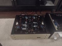
Board is mounted on heatsink. I tested the input stage and adjusted p1 and p2 to 4v each at TP7 and TP8. I am using the FQA mosfet drivers. I then proceded to step 9 and set TP5 to 1.0v. With TP5 at 1.0v setting, I checked TP7 and it is now close to 6v. Is this lining up? R13 is measuring approx 0.6mv and I used a 15ohm resistor which gives me 40ma of bias.
Attachments
Last edited:
TP7 voltage seems normal : 1V + VGS driver at about 60ma (1V/15 ohms). Your driver VGS is probably on the high side of the range.
Not sure what you mean R13 measuring 0,6mV….
Do you have 0,6V between TP6/V- ? This would give also driver current of 60ma on the negative side so similar as for the positive side.
Fab
Not sure what you mean R13 measuring 0,6mV….
Do you have 0,6V between TP6/V- ? This would give also driver current of 60ma on the negative side so similar as for the positive side.
Fab
Ok I thought by measuring the voltage drop of R13 or R14 that was the bias for the driver mosfet. I have 0.7volts between TP6 and V- so that lines up with 70ma of bias then. Looks like I am ready to drop in the output mosfets and set TP4, TP2 for 0.13mv. So basically I tested the input stage and set it for 4v. Then I tested the mosfet driver stage and turned P1, P2 some more so I achieved 1.0v at TP5 and 0.70v at TP6, when I did this is automaticalley increased TP7 and TP8 voltage measurement. I am guessing to get the 0.13mv at TP4, TP2 I will be increasing the P1,P2 trimmers again(but I havent gotten that far yet).
I am using 15ohms for RV1a and 22ohms for RV1b
I am using 15ohms for RV1a and 22ohms for RV1b
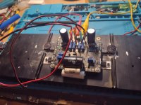
So I got a little excited and mounted the output mosfets. I can only seem to get max 9mv between TP2 to V+ and TP4 to V-. I set both sides to 8mv and measured 0v of DC offset. But thats only 0.8A of bias.
Last edited:
Most of it is ok except you keep using 0.13mv which is a very low value…unless you mean 13mv across R15 and R16 for output stage bias current (see post 121).Ok I thought by measuring the voltage drop of R13 or R14 that was the bias for the driver mosfet. I have 0.7volts between TP6 and V- so that lines up with 70ma of bias then. Looks like I am ready to drop in the output mosfets and set TP4, TP2 for 0.13mv. So basically I tested the input stage and set it for 4v. Then I tested the mosfet driver stage and turned P1, P2 some more so I achieved 1.0v at TP5 and 0.70v at TP6, when I did this is automaticalley increased TP7 and TP8 voltage measurement. I am guessing to get the 0.13mv at TP4, TP2 I will be increasing the P1,P2 trimmers again(but I havent gotten that far yet).
I am using 15ohms for RV1a and 22ohms for RV1b
Yes the manual goes safely by adjusting to low value to increase at each step until final stage to avoid overheating devices…
The total resistance between TP5 and V+ should be about 1.5 time the total resistance between TP6 and V-.
Fab
Ok after a bunch of growing pains, all induced by me and my test bench power supply lol. Mr Fab was very generous with his time and patience, helping me get to the finish line.
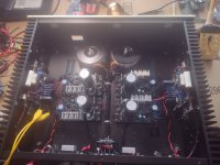
13mv across r15 and r16 for 1.3A of bias with about 5mv of offset. Both channels mounted and tested on the heatsinks ready to be installed into the case.
Dont mess up the polarity Chris.......hahahahaha.
Will post back once I get it to make actual noise into speakers.
Thank you Fab for helping us rookies!!!
Attachments

Gsrchisu ,
If you are planning on building a preamp , or more amps after this , I highly recommend buying a used scope .
Seeing a waveform lets you really know what is going on with an Amp, or the power supply rails .
At one time tektronix had a huge portion of the scope market - some of those 40 year old tektonix scopes can be bought for a song .
They were built to last. Make sure it comes with probes and know that the dials can develop intermittent contacts .
Then build a DIY generator - which does not have to be anything fancy .
I used an old 25 pin printer port switch box for the case .
You have a dual bench supply , so you'll be set .
.
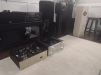
Ok finally got all the wiring figured out, set bias in the main chassis. So far is quiet and has the big sound stage everyone talks about. Have very little time on it but def sounds better than the F6 boards it replaced. Cant remember the gain for this amp but feels powerful compared to the F6 and F8. Tried without subs to test out the damping and it sounds tight, not boomy at all, better than the aleph j and M2 for sure. I really wanted this one to work, hahahah, just for the fact that I could never afford the real version which is priced at 5kcdn.
Thanks again Fab for the support, fantastic sounding amp 🙂
Thanks again Fab for the support, fantastic sounding amp 🙂
Attachments
Hi Chris
You are welcome!
Congratulations for the completion of your amp !
I am glad you seem satisfied so far. Hoping the USSA-3.2 will stay in your Conrad Johnson chassis for a while……….until next replacement…😉
USSA-3 also has its own flavour when compared to the USSA-5 series. They sound simply different.
I suppose you have good success from experience with your input caps ?
By the way, the commercial version is not this one….but be re-assured that it is not better or worse but also different. Depends on your taste.
Fab
Last edited:
Chris ,
Thanks for the comments comparing the USSA 3.2 to the Aleph J , F6 and M2 .
To be brutally honest , I thought the transformers you are using are a bit small .
If I were to build the USSA 3.2 again , I'd go with bigger power supply caps
and use those LT4320 bridge controllers that Vunce recommends.
The USSA 3.2 is one of the very few amps I 've heard that sounds great as soon as its powered on .
I left the thermistors out , so when its first switched on , the bias is only about 400 mA
and it takes about an hour to come up to a full 1.2 Amps .
But this is one the very few amps I've ever heard that sounds great as soon as it powered up .
The string section in a Piano Concerto is the best I've ever heard - no other amp I've heard is as good with orchestral strings .
I had a pair of Quick Silver mid mono blocks , with 1960's vintage tubes , and this was the closest .
Now I understand why FAB looks at the harmonic distortion .
Also , I have a Belles 150 reference power amp - it defiantly has more muscle .
But the USSA 3.2 has lower distortion .
.
Last edited:
The power supply gsrchrisu is using is a slick regulated PSU designed by @tombo56 with all the bells and whistles included, no need for monster capacitor banks. (LT4320 active rectification, RF filter, slow start, incredibly low noise and output impedance)
Uunderhill,
Check it out, you might reconsider how you plan your power supplies in the future 😉
https://www.diyaudio.com/community/...ctifier-rf-filter-and-super-regulator.420933/
Uunderhill,
Check it out, you might reconsider how you plan your power supplies in the future 😉
https://www.diyaudio.com/community/...ctifier-rf-filter-and-super-regulator.420933/
- Home
- Amplifiers
- Solid State
- USSA-3B new Version based on USSA-3