Excellent news Fab!
And it uses the same board as USSA-5, I also smell another build. 🙂
Stay Well Everybody!!
And it uses the same board as USSA-5, I also smell another build. 🙂
Stay Well Everybody!!
Thank you Claude, pinnocchio and Vunce!
Hi UltimateX86
Digikey distributor.
Digikey Canada is expecting reception of a new batch on May 3rd as indicated.
Fab
Hi UltimateX86
Digikey distributor.
Digikey Canada is expecting reception of a new batch on May 3rd as indicated.
Fab
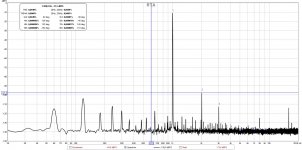
I was able to perform some measurements when boards are installed inside the chassis to replace the USSA-5.1 boards. This way I use the same PSU. This was also done this way for the USSA-5B.
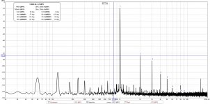
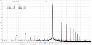
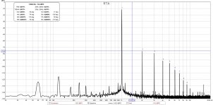
So this is the USSA-3B THD profiles into 8 ohms at 1.1A bias:
USSA3B_THD_1KHz_1Wrms.jpg
USSA3B_THD_1KHz_6Wrms.jpg
USSA3B_THD_1KHz_10Wrms.jpg
USSA3B_THD_1KHz_20Wrms.jpg
I was able to get <= 0.1% THD at 30Wrms with +/-24vdc PSU.
I have adjusted for extra H2 to impress the gallery 😛
I could have put even more if wanted 😉
Fab
Attachments
Last edited:
Do you perhaps have the same or similar graphs for USSA 5 and FFSA, for the sake of comparison?
Well done again
Claude
Well done again
Claude
I have adjusted for extra H2 to impress the gallery 😛
I could have put even more if wanted 😉
Fab
That THD profile brings a tear to my eye, nice Fab! 🙂
Hi Claude
I have 3 x USSA-5 versions and 2 x FSSA versions ....
....
See this post for USSA-5.1:
USSA-5 PCB GB
All 3 USSA-5 versions thd profiles are in the consolidated USSA-5 manual.
For the FSSA, the THD profile is kind of similar too but the numbers are much lower, see my web site for values.
The THD profile is more a side effect result of the other characteristics that I target..
H2 higher level is just the flavour of the moment in the magical search of a single criteria for good sound...😉
Fab
I have 3 x USSA-5 versions and 2 x FSSA versions
....See this post for USSA-5.1:
USSA-5 PCB GB
All 3 USSA-5 versions thd profiles are in the consolidated USSA-5 manual.
For the FSSA, the THD profile is kind of similar too but the numbers are much lower, see my web site for values.
The THD profile is more a side effect result of the other characteristics that I target..
H2 higher level is just the flavour of the moment in the magical search of a single criteria for good sound...😉
Fab
That THD profile brings a tear to my eye, nice Fab! 🙂
Thanks Vunce! I hope it is an happiness tear...😉
Fab
LOL!
Yep, H2 sounds nice I must admit, although apparently I seem to prefer 4x less of that flavour than the usual audiophile - albeit still a tad more than H3 in my case.
Thanks a lot Fab, I will browse and see all that... just as side note, I don't have sadly the USSA-5 manual.
Joyeuses Pâques
Claude
Yep, H2 sounds nice I must admit, although apparently I seem to prefer 4x less of that flavour than the usual audiophile - albeit still a tad more than H3 in my case.
Thanks a lot Fab, I will browse and see all that... just as side note, I don't have sadly the USSA-5 manual.
Joyeuses Pâques
Claude
I agree with you Claude.
In my view playing around with THD can be done in the preamp.🙄
Now back to finishing my amp before my wife tells me to do something around the house😀
In my view playing around with THD can be done in the preamp.🙄
Now back to finishing my amp before my wife tells me to do something around the house😀
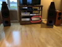
Some pictures to show the real thing...
I use ceramic insulators for the output.
During the investigation of the second board I tried the 2SC5200-O/2SA1943-O and then put back the MJL transistors. In the exact same circuit with same polarisation the latter transistors pair gave lowest distortion supposing a slightly better linearity. It could also be the difference in HFE too but I doubt it...
I started to listen to the amp since yesterday and still in break- in. Burn-in was done on Saterday.
Fab
Attachments

Last edited:
Yes they were.Interesting find regarding the output transistors.
Were the 2SA/ 2SC Toshiba?
Fab
Fab that's interesting because last year I tried matching some Toshiba 2SA970BL and 2SC2240BL and noticed that on my pretend curve tracer the curves were not as linear as the BC series transistors.
Harry3
Interesting also your finding but I do not know if we can really compare because I am referring to power transistors and you are referring to small signal ones.🙄
But I prefer also the BC for small signals anyway because they are easier to find😉
Fab
Interesting also your finding but I do not know if we can really compare because I am referring to power transistors and you are referring to small signal ones.🙄
But I prefer also the BC for small signals anyway because they are easier to find😉
Fab
As you know I prefer that others comment the sound of my amps to obtain a more objective opinion...so this might be only after.... the lockdown...🙄
Unless someone encourages me to break my own rule about commenting ... but accepting the consequences 😉
Fab
Unless someone encourages me to break my own rule about commenting ... but accepting the consequences 😉
Fab
Doesn’t sound like you need any encouragement Fab, we can read between the lines and get the feeling your liking what your hearing 😀
Vunce
You are a wise man who understands the monkey’s mind...😉
However I will wait a bit more so the break- in can be more advanced.
As a teaser I almost had a full day listening during that Easter Monday confined to my home...🙄
Fab
You are a wise man who understands the monkey’s mind...😉
However I will wait a bit more so the break- in can be more advanced.
As a teaser I almost had a full day listening during that Easter Monday confined to my home...🙄
Fab
- Home
- Amplifiers
- Solid State
- USSA-3B new Version based on USSA-3